NOTICE
External stop signals activated with control signals or a
eldbus override a start command via the LCP.
[O]
[O]
stops the connected motor. The key can be selected
as [1] Enabled or [0] Disabled via parameter 0-41 [O] Key on
LCP. If no external stop function is selected, and the [O]
key is inactive, the motor can only be stopped by discon-
necting the mains supply.
[Auto On]
[Auto On] enables the frequency converter to be controlled
via the control terminals and/or serial communication.
When a start signal is applied on the control terminals
and/or the bus, the frequency converter starts. The key can
be selected as [1] Enabled or [0] Disabled via
parameter 0-42 [Auto on] Key on LCP.
NOTICE
An active HAND-OFF-AUTO signal via the digital inputs
has higher priority than the control keys [Hand On] –
[Auto On].
[Reset]
Press [Reset] to reset the frequency converter after an
alarm (trip). It can be selected as [1] Enable or [0] Disable
via parameter 0-43 [Reset] Key on LCP.
The parameter shortcut can be carried out by pressing the
[Main Menu] key for 3 s. The parameter shortcut allows
direct access to any parameter.
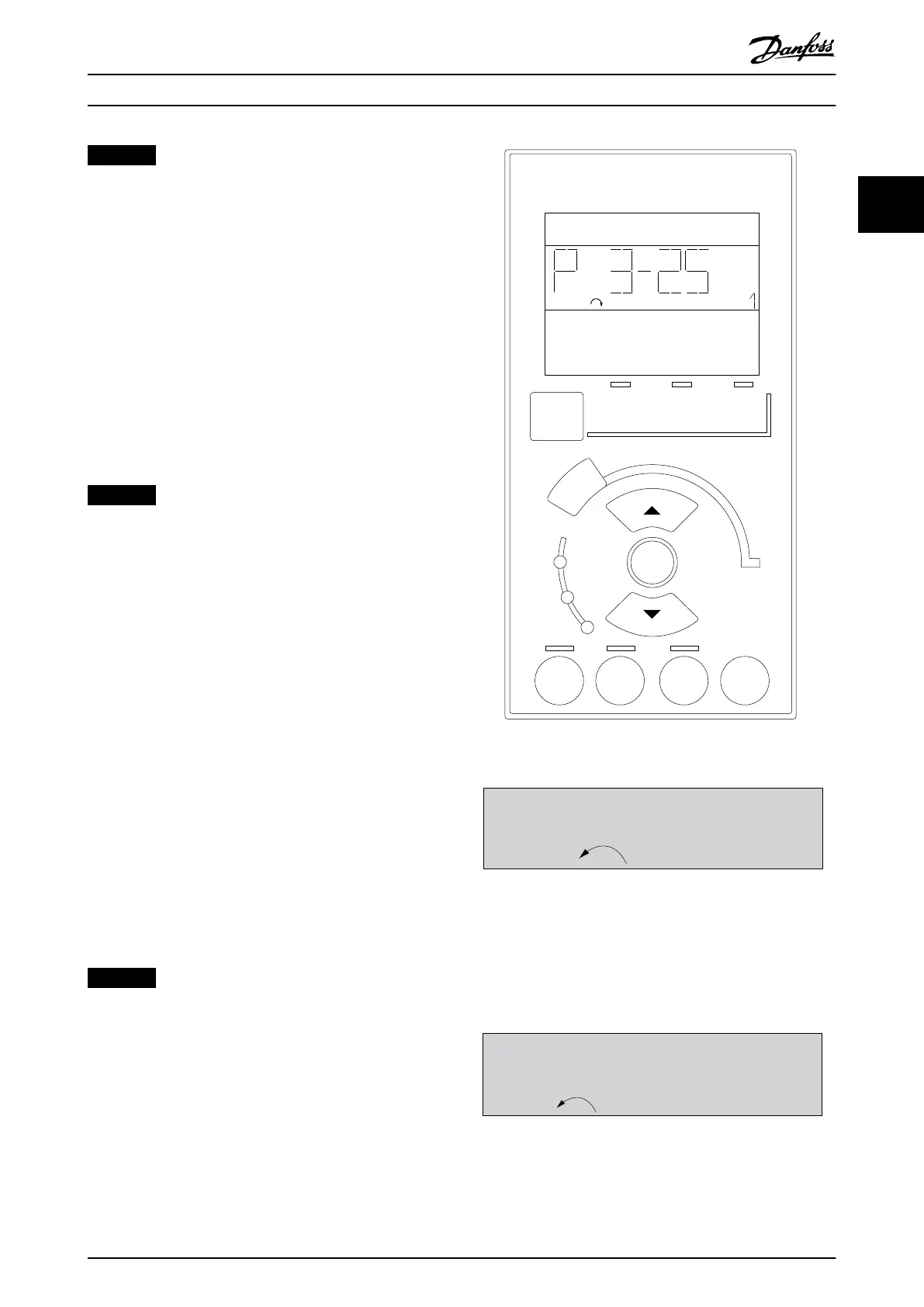
2.1.2 How to Operate Numeric LCP (NLCP)
The control panel is divided into 4 functional groups:
1. Numeric display.
2. Menu key and indicator lights (LEDs) - changing
parameters and switching between display
functions.
3. Navigation keys and indicator lights (LEDs).
4. Operation keys and indicator lights (LEDs).
NOTICE
Parameter copy is not possible with NLCP (LCP101).
Select 1 of the following modes:
Status mode: Shows the status of the frequency converter
or the motor.
If an alarm occurs, the NLCP automatically switches to
status mode.
A number of alarms can be shown.
Quick setup or main menu mode: Show parameters and
parameter settings.
e30ba191.11
1
Auto
On
Reset
Hand
On
Off
Menu
Status
Quick
Setup
Main
Menu
Back
2
3
4
OK
On
Alarm
Warn.
Setup
Illustration 2.13 Numerical LCP (NLCP)
130BP077.10
22.8
rpm
Setup 1
Illustration 2.14 Status Display Example
Indicator lights (LEDs):
•
Green LED/On: Indicates if control section is on.
•
Yellow LED/Warn.: Indicates a warning.
•
Flashing red LED/Alarm: Indicates an alarm.
Illustration 2.15 Alarm Display Example
Menu key
How to Programme Programming Guide
M0010001 Danfoss A/S © 10/2019 All rights reserved. 15
2 2
 Loading...


