The lower the power factor, the higher the I
RMS
for the
same kW performance.
I
RMS
= I
1
2
+ I
5
2
+ I
7
2
+ .. + I
n
2
In addition, a high power factor indicates that the dierent
harmonic currents are low.
The DC coils in the frequency converters produce a high
power factor, which minimizes the imposed load on the
mains supply.
Target position
The nal target position specied by positioning
commands. The prole generator uses this position to
calculate the speed prole.
Commanded position
The actual position reference calculated by the prole
generator. The frequency converter uses the commanded
position as setpoint for position PI.
Actual position
The actual position from an encoder, or a value that the
motor control calculates in open loop. The frequency
converter uses the actual position as feedback for position
PI.
Position error
Position error is the dierence between the actual position
and the commanded position. The position error is the
input for the position PI controller.
Position unit
The physical unit for position values.
1.2
Safety
WARNING
DISCHARGE TIME
The frequency converter contains DC-link capacitors,
which can remain charged even when the frequency
converter is not powered. High voltage can be present
even when the warning indicator lights are o. Failure to
wait the specied time after power has been removed
before performing service or repair work, could result in
death or serious injury.
1. Stop the motor.
2. Disconnect AC mains, permanent magnet type
motors, and remote DC-link power supplies,
including battery back-ups, UPS, and DC-link
connections to other frequency converters.
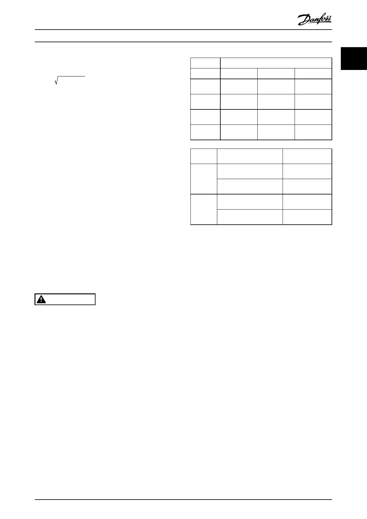
3. Wait for the capacitors to discharge fully, before
performing any service or repair work. The
duration of waiting time is specied in Table 1.4.
Voltage [V] Minimum waiting time (minutes)
4 7 15
200–240 0.25–3.7 kW
(0.34–5 hp)
– 5.5–37 kW
(7.5–50 hp)
380–500 0.25–7.5 kW
(0.34–10 hp)
– 11–75 kW
(15–100 hp)
525–600 0.75–7.5 kW
(1–10 hp)
– 11–75 kW
(15–100 hp)
525–690 – 1.5–7.5 kW
(2–10 hp)
11–75 kW
(15–100 hp)
Voltage
[V]
Power Minimum waiting
time (minutes)
380–500 90–250 kW
(125–350 hp)
20
315–800 kW
(450–1075 hp)
40
525–690 55–315 kW (frame size D)
(75–450 hp)
20
355–1200 kW
(475–1600 hp)
30
Table 1.4 Discharge Time
Safety regulations
•
Disconnect mains supply to the frequency
converter whenever repair work is to be carried
out. Check that the mains supply has been
disconnected and that the necessary time has
elapsed before removing motor and mains supply
plugs. For information about the discharge time,
see Table 1.4.
•
[O] does not disconnect the mains supply and
must not be used as a safety switch.
•
Ground the equipment properly, protect the user
against supply voltage, and protect the motor
against overload in accordance with applicable
national and local regulations.
•
The ground leakage current exceeds 3.5 mA.
Ensure correct grounding of the equipment by a
certied electrical installer.
•
Do not remove the plugs for the motor and
mains supply while the frequency converter is
connected to mains. Check that the mains supply
has been disconnected and that the necessary
time has elapsed before removing motor and
mains plugs.
•
The frequency converter has more voltage
sources than L1, L2, and L3, when load sharing
(linking of DC intermediate circuit) or external
24 V DC is installed. Check that all voltage
sources have been disconnected and that the
necessary time has elapsed before commencing
repair work. For information about the discharge
time, see Table 1.4.
Introduction Programming Guide
M0010001 Danfoss A/S © 10/2019 All rights reserved. 9
1 1
 Loading...


