3.20.3 22-4* Sleep Mode
If the load on the system allows for stop of the motor and
the load is monitored, the motor can be stopped by
activating the sleep mode function. This is not a normal
stop command, but ramps the motor down to 0 RPM and
stops energizing the motor. When in sleep mode, certain
conditions are monitored to nd out when load has been
applied to the system again.
Sleep mode can be activated either from the
no-ow
detection/minimum speed detection (must be
programmed via parameters for no-ow detection, see the
signal ow-diagram in parameter group 22-2* No-Flow
Detection) or via an external signal applied to 1 of the
digital inputs (must be programmed via the parameters for
conguration of the digital inputs, parameter group 5-1*
Digital Inputs selecting [66] Sleep Mode). Sleep mode is
activated only when no wake-up conditions are present.
To enable use of, for example, an electro-mechanical ow
switch to detect a no-ow condition and activate sleep
mode, the action takes place at the raising edge of the
external signal applied (otherwise the frequency converter
would stay in sleep mode as the signal would be steadily
connected).
NOTICE
If sleep mode is to be based on no-ow detection/
minimum speed, select [1] Sleep Mode in
parameter 22-23 No-Flow Function.
If parameter 25-26 Destage At No-Flow is set for [1] Enabled,
activating sleep mode sends a command to the cascade
controller (if enabled) to start de-staging of lag pumps
(xed speed) before stopping the lead pump (variable
speed).
When entering sleep mode, the lower status line in the
LCP shows Sleep Mode.
See also signal
ow chart in parameter group 22-2* No-Flow
Detection.
There are the following ways of using the sleep mode
function:
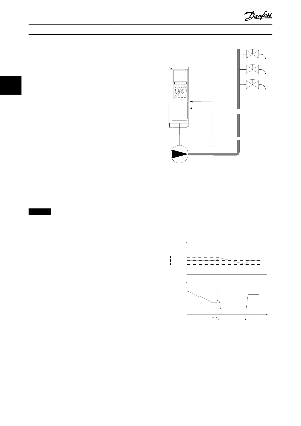
Illustration 3.57 Sleep Mode Function
1) Systems where the integrated PI controller is used for
controlling pressure or temperature, for example, boost
systems with a pressure feedback signal applied to the
frequency converter from a pressure transducer. Set
parameter 1-00 Conguration Mode for [3] Closed Loop and
congure the PI controller congured for desired reference
and feedback signals.
Example: Boost system.
p (Pressure)
Time
Time
No/Low Flow
detected
P 22-45
P 22-44
Sleep mode
activated
Boost
activated
P
Boost
P
Set
P
Wake
f
Ref
f
out
(Frequency)
P
System
130BA257.10
t
1
p
System
= p
Wake
Illustration 3.58 Boost System
If no-ow is detected, the frequency converter increases
the setpoint for pressure to ensure a slight overpressure in
the system (boost set in parameter 22-45 Setpoint Boost).
The feedback from the pressure transducer is monitored,
and when this pressure has dropped with a set percentage
below the normal setpoint for pressure (P
set
), the motor
Parameter Descriptions
VLT
®
HVAC Drive FC 102
204 Danfoss A/S © 10/2019 All rights reserved. M0010001
33
 Loading...


