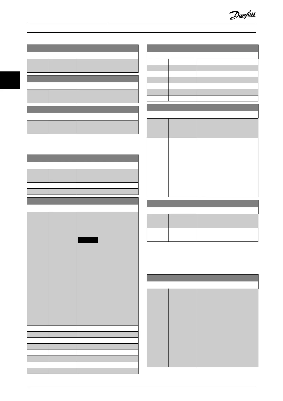
13-97 Alert Alarm Word
Range: Function:
0* [0 -
4294967295 ]
Shows the alarm word of a user-
dened alarm in hex code.
13-98 Alert Warning Word
Range: Function:
0* [0 -
4294967295 ]
Shows the warning word of a user-
dened alarm in hex code.
13-99 Alert Status Word
Range: Function:
0* [0 -
4294967295 ]
Shows the status word of a user-
dened alarm in hex code.
3.14 Parameters: 14-** Main Menu - Special
Functions
14-00 Switching Pattern
Option: Function:
Select the switching pattern: 60°
AVM or SFAVM.
[0] 60 AVM
[1] SFAVM
14-01 Switching Frequency
Option: Function:
Select the inverter switching
frequency. Changing the switching
frequency can help reduce acoustic
noise from the motor.
NOTICE
The output frequency value of
the frequency converter must
never exceed 1/10 of the
switching frequency. When the
motor is running, adjust the
switching frequency in
parameter 14-01 Switching
Frequency until the motor is as
noiseless as possible. See also
parameter 14-00 Switching
Pattern. For information about
derating, see the relevant
design guide.
[0] 1.0 kHz
[1] 1.5 kHz
[2] 2.0 kHz
[3] 2.5 kHz
[4] 3.0 kHz
[5] 3.5 kHz
[6] 4.0 kHz
[7] 5.0 kHz
14-01 Switching Frequency
Option: Function:
[8] 6.0 kHz
[9] 7.0 kHz
[10] 8.0 kHz
[11] 10.0 kHz
[12] 12.0kHz
[13] 14.0 kHz
[14] 16.0kHz
14-03 Overmodulation
Option: Function:
[0] * O Selects no overmodulation of the
output voltage to avoid torque
ripple on the motor shaft.
[1] On The overmodulation function
generates an extra voltage of up to
8% of U
max
output voltage without
overmodulation. This extra voltage
results in an extra torque of 10–
12% in the middle of the oversyn-
chronous range (from 0% at
nominal speed, rising to approxi-
mately 12% at double nominal
speed).
14-04 Acoustic Noise Reduction
Option: Function:
[0] * O No change of the acoustic motor
switching noise.
[1] On Select to reduce the acoustic noise
from the motor.
3.14.1 14-1* Mains On/O
Parameters for conguring mains failure monitoring and
handling.
14-10 Mains Failure
Option: Function:
Select the function at which the
frequency converter must act, when
the threshold set in
parameter 14-11 Mains Fault Voltage
Level has been reached or a mains
failure inverse command is
activated via 1 of the digital inputs
(parameter group 5-1* Digital Inputs).
Only selection [0] No function, [3]
Coasting, or [6] Alarm is available
when parameter 1-10 Motor
Construction is set to [1] PM non-
salient SPM.
Parameter Descriptions
VLT
®
HVAC Drive FC 102
146 Danfoss A/S © 10/2019 All rights reserved. M0010001
33
 Loading...


