Terminal number 53 (201), 54 (202)
Modes Voltage or current
Mode select Switch A53 (S201) and switch A54 (S202)
Voltage mode Switch A53 (S201)/A54 (S202) = OFF (U)
Voltage level -10 V to +10 V (scaleable)
Input resistance, R
i
Approximately 10 kΩ
Maximum voltage ±20 V
Current mode Switch A53 (S201)/A54 (S202) = ON (I)
Current level 0/4 to 20 mA (scaleable)
Input resistance, R
i
Approximately 200 Ω
Maximum current 30 mA
Resolution for analog inputs 10 bit (+ sign)
Accuracy of analog inputs Maximum error 0.5% of full scale
Bandwidth 100 Hz
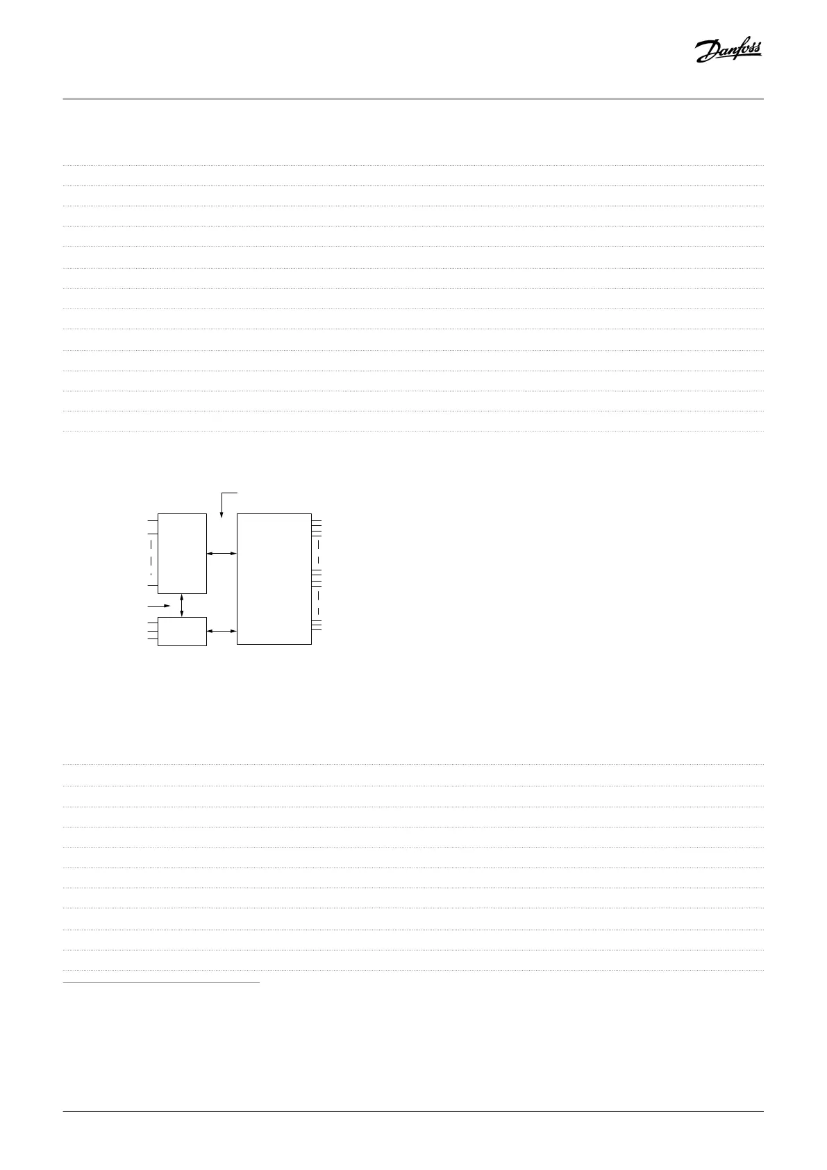
The analog inputs are galvanically isolated from the supply voltage (PELV) and other high-voltage terminals.
Functional
isolation
PELV isolation
Motor
DC-bus
High
voltage
+24 V
RS485
18
37
e30ba117.11
Illustration 51: PELV Isolation
9.6.4 Pulse/encoder Inputs
Programmable pulse/encoder inputs 2/1
Terminal number (pulse)
29
(1)
, 33
Terminal number (encoder)
32, 33
(2)
Maximum frequency at terminals 29, 32, 33 110 kHz (Push-pull driven)
Maximum frequency at terminals 29, 32, 33 5 kHz (Open collector)
Maximum frequency at terminals 29, 32, 33 4 Hz
Voltage level See Digital Inputs.
Maximum voltage on input 28 V DC
Input resistance, R
i
Approximately 4 kΩ
Pulse input accuracy (0.1–1 kHz) Maximum error: 0.1% of full scale
Encoder input accuracy (1–11 kHz) Maximum error: 0.05% of full scale
1
FC 302 only.
2
Encoder inputs: 32=A and 33=B.
Specifications
Operating Guide | VLT® Refrigeration Drive FC 103
AQ275652766279en-000101 / 130R0707| 135
Danfoss A/S © 2020.01
 Loading...


