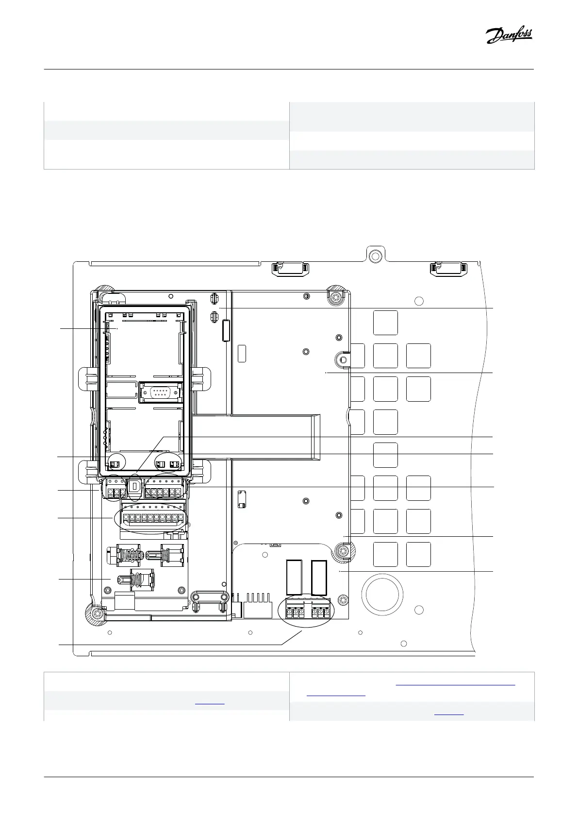
9 Fans (used to cool the front section of enclosure)
11 Space heater (optional)
13 Motor terminals
8 RFI shield termination (optional, but is standard when RFI
filter is ordered)
10 Fan power card
12 Brake terminals (optional)
Illustration 3: Interior View of Enclosure E3h (Enclosure E4h is Similar)
3.4 Control Shelf
e30bf148.11
Remove Jumper to activate Safe Stop
12 13 18 19 27 29 32 33 20 37
39 42 50 53 54 55
RELAY 1 RELAY 2
01 02
03
04 05 06
1 LCP cradle (LCP not shown)
3 Serial communication terminals (see table 10)
2 Bus terminal switch (see 5.11.8.2 Configuring RS485 Serial
Communication)
4 Digital input/output terminals (see table 11)
Product Overview
Operating Guide | VLT® Refrigeration Drive FC 103
AQ275652766279en-000101 / 130R0707
16 | Danfoss A/S © 2020.01
 Loading...


