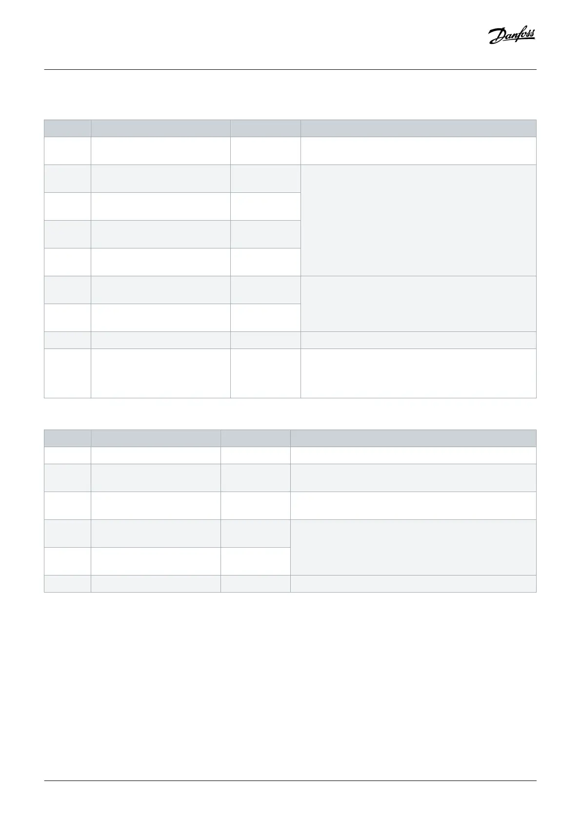
Table 11: Digital Input/Output Terminal Descriptions
Terminal Parameter Default setting Description
12, 13 – +24 V DC 24 V DC supply voltage for digital inputs and external trans-
ducers. Maximum output current 200 mA for all 24 V loads.
18 Parameter 5-10 Terminal 18 Digital
Input
[8] Start Digital inputs.
19 Parameter 5-11 Terminal 19 Digital
Input
[10] Reversing
32 Parameter 5-14 Terminal 32 Digital
Input
[0] No operation
33 Parameter 5-15 Terminal 33 Digital
Input
[0] No operation
27 Parameter 5-12 Terminal 27 Digital
Input
[2] Coast inverse For digital input or output. Default setting is input.
29 Parameter 5-13 Terminal 29 Digital
Input
[14] JOG
20 – – Common for digital inputs and 0 V potential for 24 V supply.
37 – STO When not using the optional STO feature, a jumper wire is re-
quired between terminal 12 (or 13) and terminal 37. This set-
up allows the drive to operate with factory default program-
ming values.
Table 12: Analog Input/Output Terminal Descriptions
Terminal Parameter Default setting Description
39 – – Common for analog output.
42 Parameter 6-50 Terminal 42 Out-
put
[0] No operation Programmable analog output. 0–20 mA or 4–20 mA at a maxi-
mum of 500 Ω.
50 – +10 V DC 10 V DC analog supply voltage for potentiometer or thermistor.
15 mA maximum.
53 Parameter group 6-1* Analog In-
put 1
Reference Analog input. For voltage (V) or current (mA).
54 Parameter group 6-2* Analog In-
put 2
Feedback
55 – – Common for analog input.
5.11.4 Relay Terminals
• Relays 1 and 2 are standard relay terminals included on all drives. The location of the outputs depends on the drive configuration.
See the Control Shelf section.
• If a drive is configured with built-in optional equipment, more terminals may be included. Refer to the manual provided with the
optional equipment.
Electrical Installation
Operating Guide | VLT® Refrigeration Drive FC 103
AQ275652766279en-000101 / 130R0707
58 | Danfoss A/S © 2020.01
 Loading...


