5 Cable/EMC clamps
7 Control card (underneath LCP and control terminals)
9 USB port
11 Analog input/output terminals (see table 12)
13 Power card (underneath the control shelf )
6 Relay 1 and relay 2 (see 5.11.4 Relay Terminals)
8 Control shelf
10 Analog input switches A53/A54 (see 5.11.13 Selecting the
Voltage/Current Input Signal)
12 Brake resistor terminals, 104–106 (on power card
underneath control shelf )
Illustration 4: View of Control Shelf
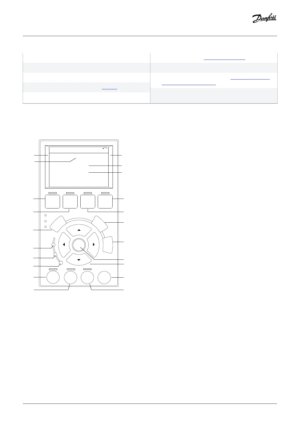
3.5 Local Control Panel (LCP)
e30bf155.10
Auto
On
Reset
Hand
On
Off
A3
B1
B2
B4
B3
C1
C2
C3
C4
C5
D1
D2
D3
E1
E2
E3
E4
Illustration 5: Graphical Local Control Panel (LCP)
The local control panel (LCP) is the combined display and keypad on the front of the drive. The LCP is used to:
• Control the drive and motor.
• Access drive parameters and program the drive.
• Display operational data, drive status, and warnings.
A numeric local control panel (NLCP) is available as an option. The NLCP operates in a manner similar to the LCP, but there are
differences. For details on how to use the NLCP, see the product-specific programming guide.
Product Overview
Operating Guide | VLT® Refrigeration Drive FC 103
AQ275652766279en-000101 / 130R0707| 17
Danfoss A/S © 2020.01
 Loading...


