A. Display area
Each display readout has a parameter associated with it. See table 3. The information shown on the LCP can be customized for specific
applications. Refer to My Personal Menu in the LCP Menu section.
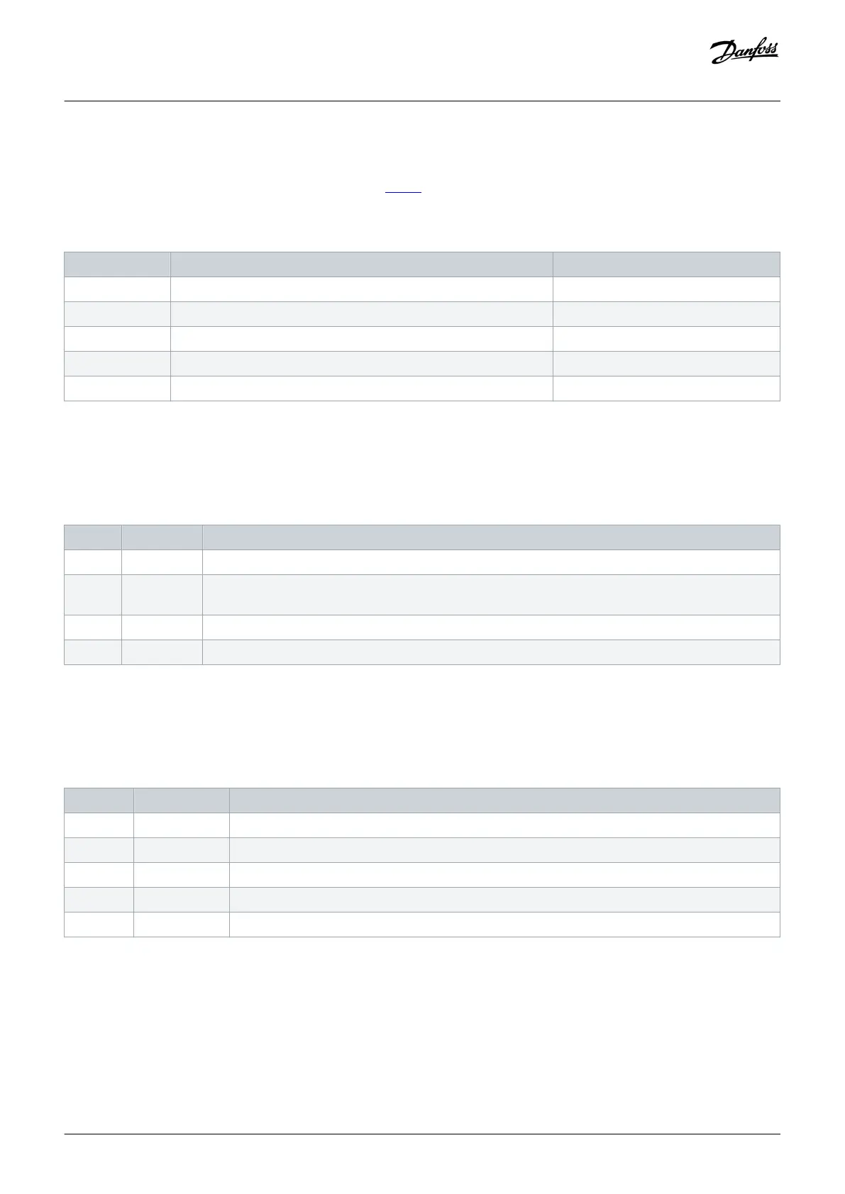
Table 3: LCP Display Area
Callout Parameter Default setting
A1.1 Parameter 0-20 Display Line 1.1 Small ReferenceSpeed [%]
A1.2 Parameter 0-21 Display Line 1.2 Small Motor current [A]
A1.3 Parameter 0-22 Display Line 1.3 Small Power [kW]
A2 Parameter 0-23 Display Line 2 Large Frequency [Hz]
A3 Parameter 0-24 Display Line 3 Large kWh counter
B. Menu keys
Menu keys are used to access the menu for setting up parameters, toggling through status display modes during normal operation,
and viewing fault log data.
Table 4: LCP Menu Keys
Callout Key Function
B1 Status Shows operational information.
B2 Quick Menu Allows access to parameters for initial set-up instructions. Also provides detailed application steps. Refer
to Quick Menu mode in the LCP Menu section.
B3 Main Menu Allows access to all parameters. Refer to Main Menu mode in the LCP Menu section.
B4 Alarm Log Shows a list of current warnings and the last 10 alarms.
C. Navigation keys
Navigation keys are used for programming functions and moving the display cursor. The navigation keys also provide speed control in
local (hand) operation. The display brightness can be adjusted by pressing [Status] and [▵]/[▿] keys.
Table 5: LCP Navigation Keys
Callout Key Function
C1 Back Reverts to the previous step or list in the menu structure.
C2 Cancel Cancels the last change or command as long as the display mode has not changed.
C3 Info Shows a definition of the function being shown.
C4 OK Accesses parameter groups or enables an option.
C5 [▵][▹] [▿] [◃] Moves between items in the menu.
D. Indicator lights
Indicator lights identify the drive status and provide a visual notification of warning or fault conditions.
Product Overview
Operating Guide | VLT® Refrigeration Drive FC 103
AQ275652766279en-000101 / 130R0707
18 | Danfoss A/S © 2020.01
 Loading...


