7 Wiring Configuration Examples
7.1 Application Examples
The examples in this section are intended as a quick reference for common applications.
• Parameter settings are the regional default values unless otherwise indicated (selected in parameter 0-03 Regional Settings).
• Parameters associated with the terminals and their settings are shown next to the drawings.
• Required switch settings for analog terminals A53 or A54 are also shown.
7.1.1 Wiring Configuration for Automatic Motor Adaptation (AMA)
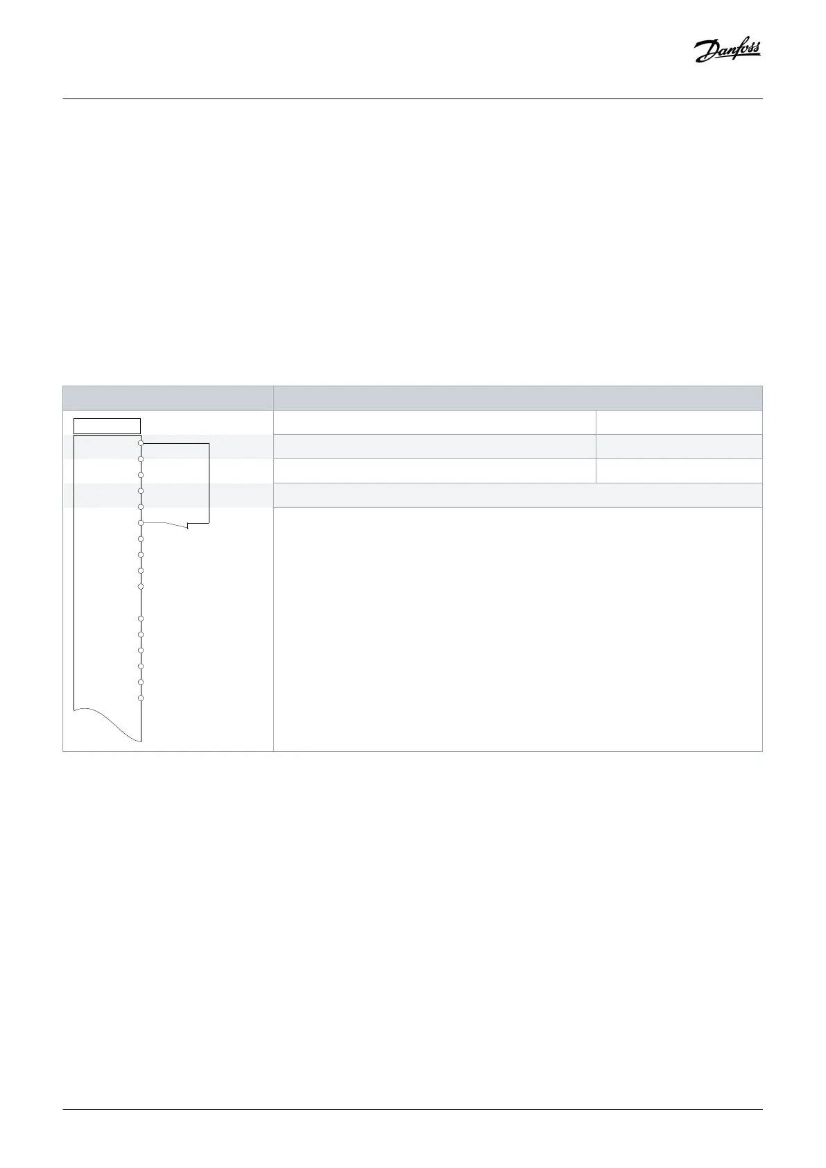
Table 16: Wiring Configuration for AMA with T27 Connected
Parameters
+24 V
+24 V
D IN
D IN
D IN
COM
D IN
D IN
D IN
D IN
+10 V
A IN
A IN
COM
A OUT
COM
12
13
18
19
20
27
29
32
33
37
50
53
54
55
42
39
e30bb929.11
Function Setting
Parameter 1-29 Automatic Motor Adaptation (AMA) [1] Enable complete AMA
Parameter 5-12 Terminal 27 Digital Input [2]* Coast inverse
*=Default value
Notes/comments:
Set parameter group 1-2* Motor Data according to motor nameplate.
Wiring Configuration Examples
Operating Guide | VLT® Refrigeration Drive FC 103
AQ275652766279en-000101 / 130R0707| 73
Danfoss A/S © 2020.01

 Loading...


