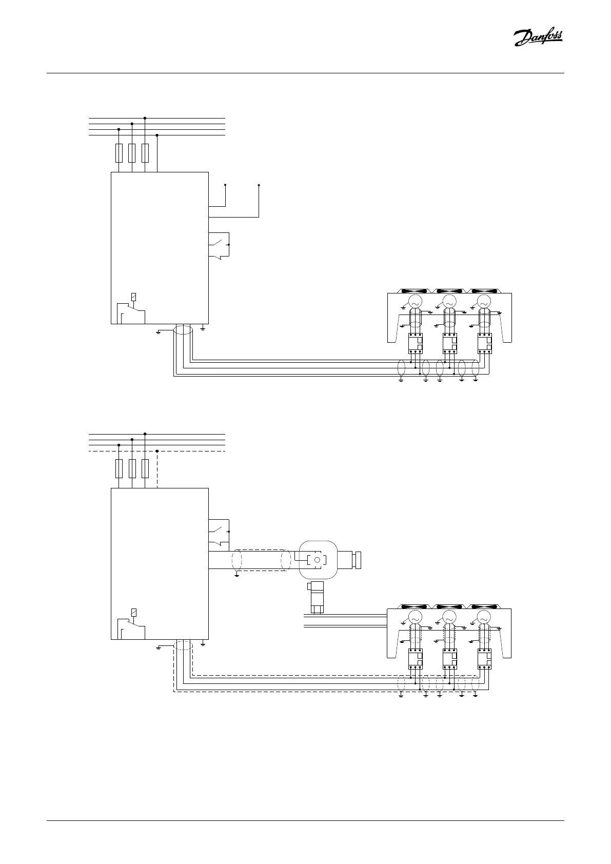
Motor
U V W PE
96 97 95 93
Cables
Ltot. max. = 40 mm
53/54
12
18
55
27
Control signal
0-10 V or
4-20 mA
Motors insulation class B minimum
Alarm
Illustration 43: Speed Control Using Analog Reference (Open Loop) – Single Fan or Pump/Multiple Fans or Pumps in Parallel
Motor
U V W PE
96 97 95 93
Cables
Ltot. max. = 40 mm
12
18
55
27
Motors insulation class B minimum
Illustration 44: Pressure Control in Closed Loop – Standalone System - Single Fan or Pump/Multiple Fans or Pumps in Parallel
Recommended motor cable types are:
Wiring Configuration Examples
Operating Guide | VLT® Refrigeration Drive FC 103
AQ275652766279en-000101 / 130R0707
92 | Danfoss A/S © 2020.01
 Loading...


