Tally Dascom 5130P
54
7.2 Interfaces
Parallel interface, serial interface and USB interface are the standard interfaces for the printer.
The interface pin assignment is listed below. (The signal with overline indicates low true logic level.)
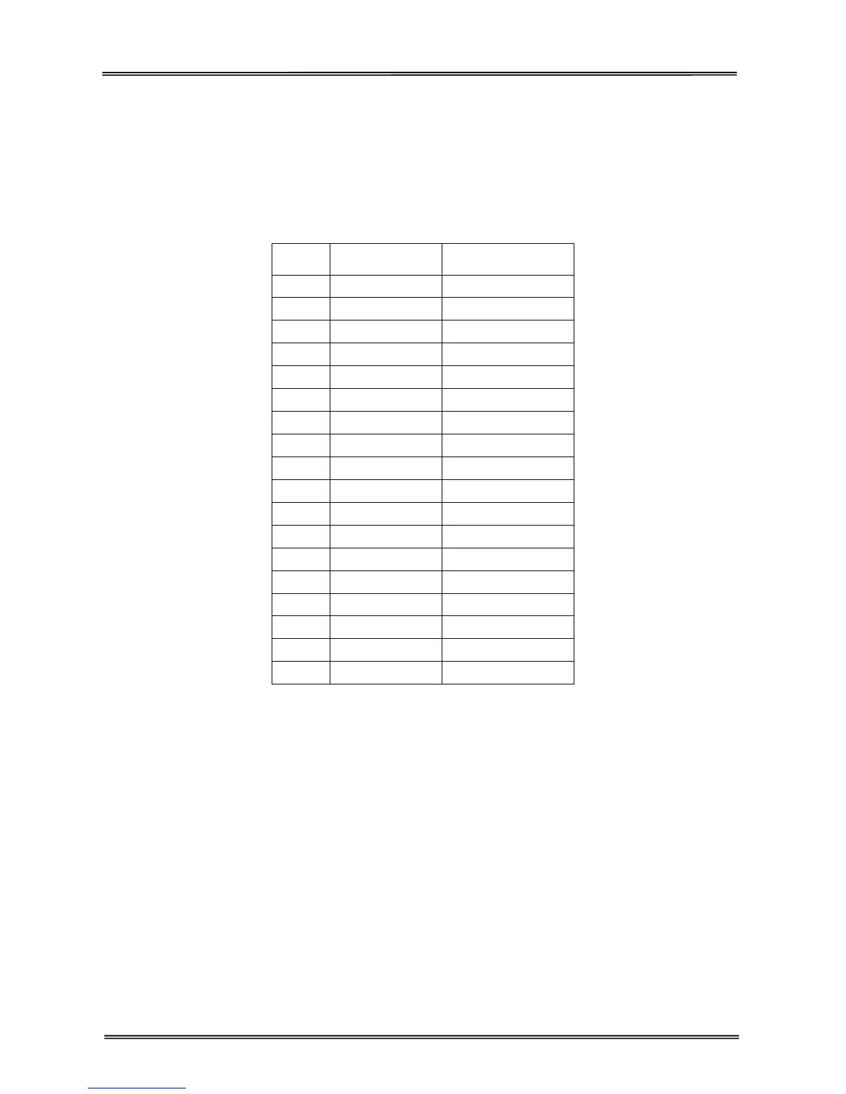
7.2.1 Parallel interface
Parallel interface pin assignment
Pin
Signal Name
Signal
Tr a n s m i s s i o n
1 STROBE ¯¯¯¯¯¯¯
Printer I Computer
2~9 DATA
Printer I Computer
10 ACK ¯¯¯
Printer J Computer
11 BUSY
Printer J Computer
12 PE
Printer J Computer
13 SELECT
Printer J Computer
14 AFXT ¯¯¯¯
Printer I Computer
15
Unused Unused
16 GND
Printer Q Computer
17 F-GND
Printer Q Computer
18 +5V
Printer J Computer
19~30 GND
Printer Q Computer
31 INIT ¯¯¯
Printer I Computer
32 FAULT ¯¯¯¯¯
Printer J Computer
33 GND
Printer Q Computer
34
Unused Unused
35 FUSE
Printer J Computer
36 SLCTIN ¯¯¯¯¯¯
Printer I Computer
STROBE¯¯¯¯¯¯¯¯¯
Normally synchronous input signal is used to prompt that the data is sending to the port. Normal state
is high logic level, while low logic level indicates DATA1~DATA8 will read the current data. The minimum
pulse width is 0.5 microsecond.
DATA1~DATA8
Signals to receive data sent from host. Logic 1 is high level and the minimum pulse width is 1.5
microseconds. DATA1 is least significant bit while DATA8 is most significant bit.
ACK¯¯¯
Signal to request sending data from host. ACK acts as the output signal when the printer is ready for
receiving new data after previous data is read and saved in DATA 1~DATA8. Normal state is high logic
level. After activating, it turns to low logic level. The pulse width is about 4 microseconds.