Tally Dascom 5130P
57
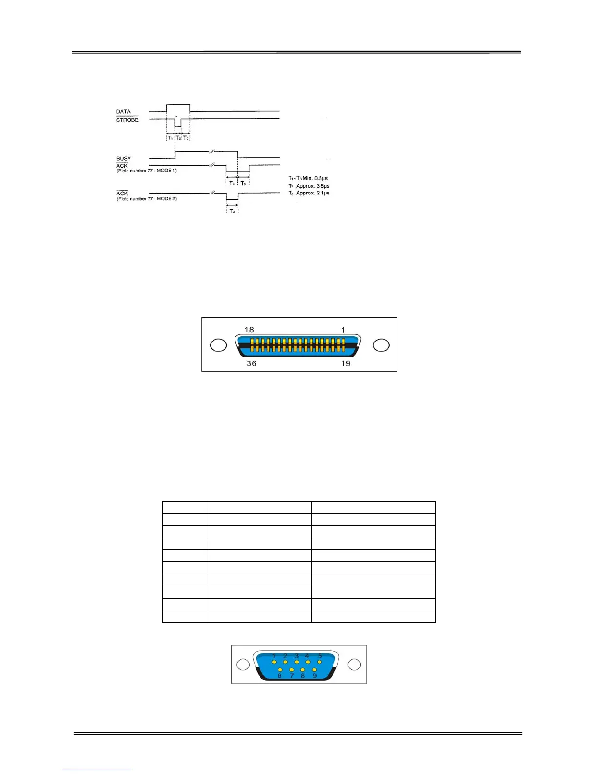
Clock and signal logic level
Clock
Signal logic level
Input: high logic level: 2~5V low logic level: 0~0.8V
Output: high logic level: 2.4~5V low logic level: 0~0.4V
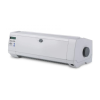
Parallel interface connector diagram
Note:
1. Use a standard parallel interface cable to connect the printer and the computer. The length should not
exceed 2 meters. Connect the 25P plug to the computer, and connect the 36P plug to the printer.
2. Normally PR2-Olivetti emulation does not support parallel printing mode. Please use serial interface to
print.
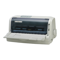
7.2.2 Serial interface
Serial interface pin assignment
Pin Signal name Description
1
2 RXD Receive data
3 TXD Send data
4 DTR Data terminal ready
5 SGND Signal ground
6 DSR Data set ready
7 RTS Request to send
8 CTS Clear to send
9
Serial interface connector diagram