Introduction
4
Gryphon™ I GD44XX/GBT4400/GM440X
The BC40xx™ Radio Base
Base LEDs
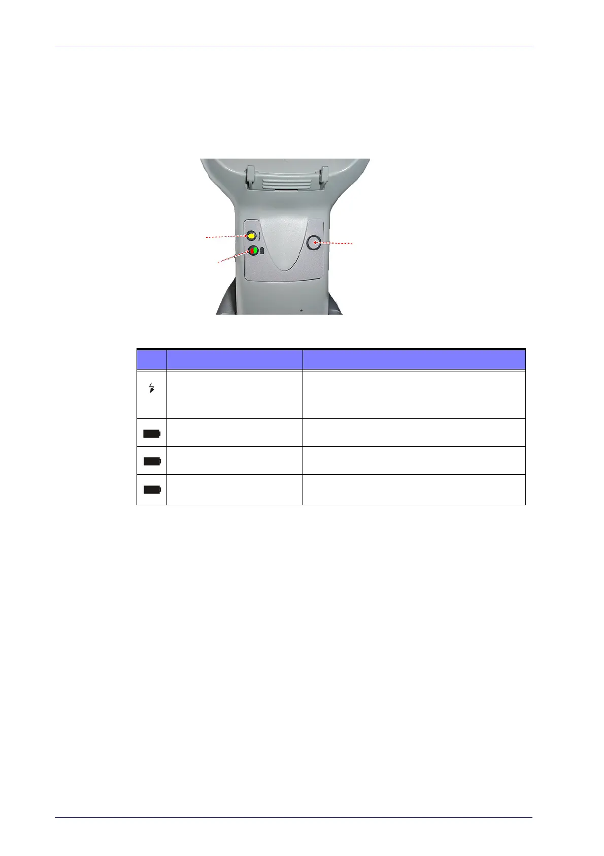
LEDs on the Gryphon Base provide information about the Base’s status, as
shown in Figure 1.
Figure 1
YELLOW LED
RED LED /
GREEN LED
BUTTON
. Gryphon Base LEDs
The following table describes the significance of each LED:
LED STATUS
Power on / Data
Yellow On = Base is powered
Yellow Blinking = Base receives data and
commands from the Host or the Reader.
Charging Red On = Battery charging is in progress.
Charge completed Green On = the Battery is completely charged.
Charging + Charge completed
Red and Green Blinking together = the Reader is
n
ot correctly placed onto the Base.
See "Base Station Indications (Cordless Models ONLY)" on page 318 for more
specific details on the LEDs.
Base Button
The Base contains a button which is used primarily to perform a paging
function. Pressing the button causes a sound signal to be emitted by all
scanners linked with this Base, as long as the scanner is awake (see "Power-
down Timeout" on page 266) and reception is en
abled (see "LED and Beeper
Indicators" on page 104). The button can also be used
to "force device con-
nection" via the Datalogic Aladdin Software tool (available for free download
fr
om the Datalogic website). See the Aladdin Online Help for details.
See "Base Station Button Indicators" on page A-318 for further information
on Base Button functions.

 Loading...