Set-Up & Installation
Product Reference Guide 2-35
4. Disconnect the Load Cell harness.
5. Move the Load Cell/Spider Assembly into position on the opposite
side of the scanner cavity and re-install the original screws. Torque
the screws evenly to 50 in-lb.
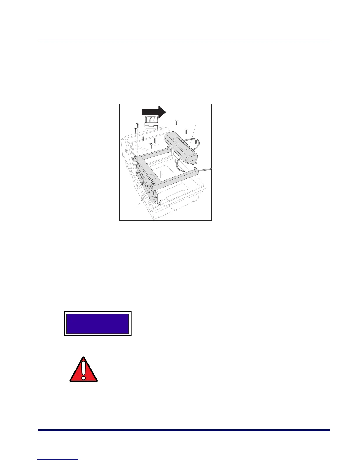
Figure 2-19. Locating the EAS Single-Antenna (Left-to-Right)
6. Route the Load Cell harness, re-bending it as indicated on the har-
ness, and reconnect.
7. Orient the EAS Antenna in the position indicated by Figure 2-17,
then route the antenna cable down through the unit’s side. Securely
attach the antenna using the screws provided.
8. Connect the antenna cable to the EAS Controller Box.
9. Re-install the platter.
This completes the EAS Single-Antenna location swapping procedure.
EAS Antenna
Product FlowProduct Flow
Load Cell/Spider
Assembly
Load Cell Harness
(bend for left-hand
scale installation)
The scale must be recalibrated upon completion of this proce-
dure, or upon completion of installation.
WARNING
DO NOT touch EAS Antenna coils inside of housing when in operation. Coils
generate over 500 VDC when activated.
 Loading...