M7/M7L/M7LT Modular Satellite Modem Maintenance
M7/M7L/M7LT - Rev. 0.05 3-89
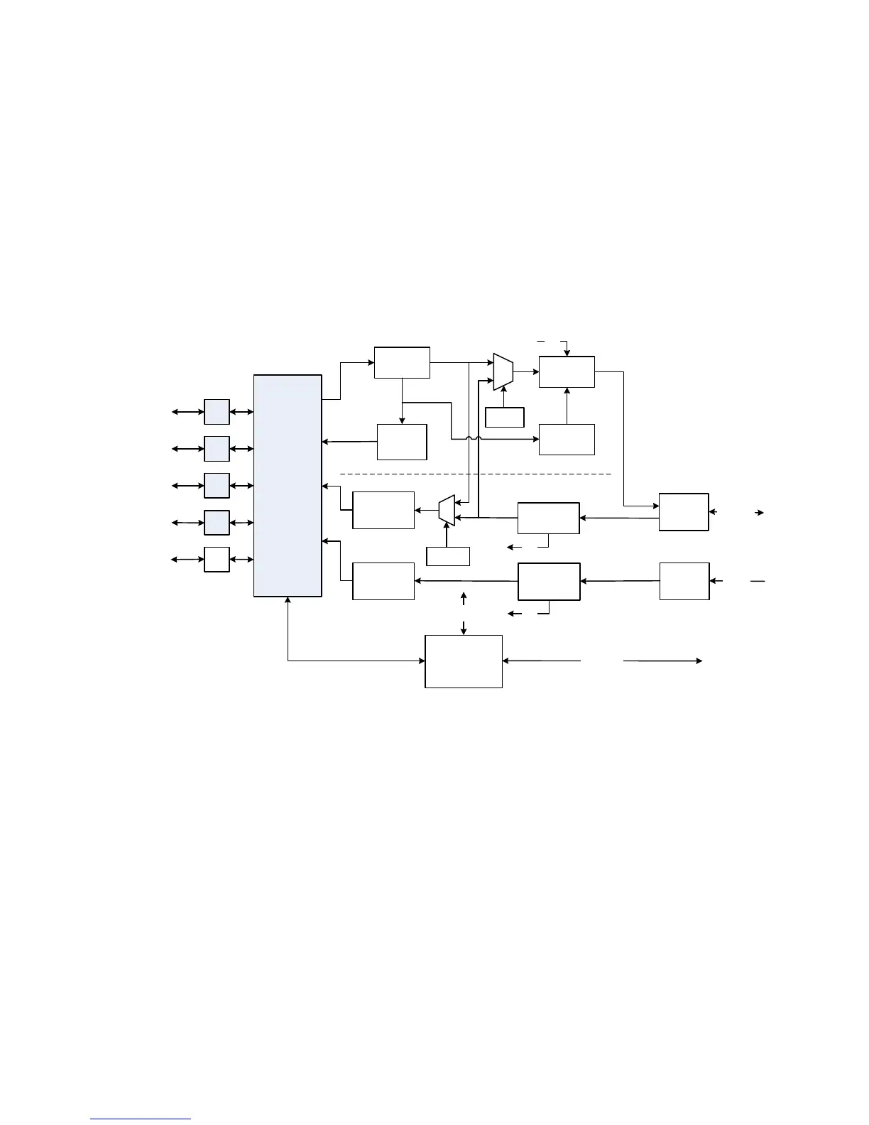
3.8.2. Express Ethernet Interface (E7)
The E7 Express Ethernet interface is a layer 2 Ethernet bridge that provides high speed switched
Ethernet capability to the M7. The E7 interface does not provide any IP routing functionality.
The purpose of the E7 is to act as an interface for up to four (4) Ethernet LAN ports within a single
satellite modems as part of point-to-point or point-to-multipoint satellite network. The E7 also offers a
fifth interface port that complies with the Small Form-factor Pluggable (SFP) standard. The SFP port
will allow interfacing to optical interfaces or will add an additional GbE port to the M7.
Detailing the internal design criteria and future capabilities of these cards is beyond the scope of this
section. Instead this section will provide an overview of the card functionality and provide typical
network configurations where this card is used within a satellite network. A simplified block diagram
is shown in Figure 3-44.
Figure 3-44 - Express Ethernet Interface Block Diagram
3.8.2.1. Gigabit Ethernet Ports 1 Through 4
The physical interface connectors for Ports 1 - 4 are conventional RJ-45 10/100/1000 copper
interfaces. The connectors interface to four (4) ports of the multi-port internal Ethernet switch.
Each port can be activated by the menu <Intf: I/O Port x Mode = Data I/O> (x=1 to 4). If a port is not
being used, the port can be disabled by the menu <Intf: I/O Port x Mode = Disabled> (x=1 to 4). If
the E7 interface is installed in a multi-demod M7, the configuration of the ports will need to reflect the
data flow from the multi-demod(s) to the central router. This will be typical of a point to multipoint
network where the Hub site has a single modulator and multiple demodulators. In this case, the hub
router would need to interface to a single transmit port and multiple demod ports. Using the menu
<Intf: I/O Port x Mode = Dmd Output I/O> (x=1 to 4) and menu <Intf: I/O Port x Mode = Dmd Input
I/O> (x=1 to 4), the multiple demodulator output data ports can be connected to the single router port
by using the internal Ethernet switch within the E7 interface. This configuration will be explained in
more detail in the network configuration discussion in Section 0
The type of connection for each port can be configured independently in the menu <Intf: I/O Port x
Connection = Auto> (x=1 to 4). . The most common setting for a port once it is activated will be
RJ45
RJ45
SFP
Cage
Port 5
1000Base-X
Optical
GbE Multi-Port
Switch
M7 Controller
Recepticle for
Optional SFP
Interface
Transmit
Receive
CPU Section
Internal
Monitor & Control
RJ45
RJ45
Port 4
10/100/
1000Base-T
Idle Frame
Generator
Congestion
feedback
Slot A
Interface
Dmd 1 HDLC
Dmd 1 to
GbE Swtich
Dmd 2 to
GbE Switch
From M7
Dmd 2
CPU Interface
Ter WAN
Loopback
SAT WAN
Loopback
Port 2
10/100/
1000Base-T
Port 1
10/100/
1000Base-T
QoS Buffer
Mod HDLC
To/From M7
Mod/Dmd
Slot B
Interface
Dmd 2 HDLC
MCC
MCC
MCC
Port 3
10/100/
1000Base-T