M7/M7L/M7LT Modular Satellite Modem Maintenance
M7/M7L/M7LT - Rev. 0.05 2-9
2.3.8. Data Interface Options
The modem is supplied with an electronically programmable data interface assembly
2.3.8.1. Synchronous Serial Data Interface
2.3.8.1.1. Synchronous Serial Data Interface Connection (J11):
The connection to the primary data signals on the Synchronous Serial Data Interface is on a 25-pin
female “D” sub connector. The physical connector and pinout is per the RS-530 interface standard.
The electrical interface however can be changed under front panel or remote program control to
include the types of interfaces shown above.
NOTE: Connecting the Data Interface to other types of equipment involves building cables between
the M7 and that other equipment’s physical interface. Additional information aiding the
creation of adaptor cables from the modem’s 25-pin female “D” sub connector to other types
of interface connections such as V.35 “Winchester” type connector standard pin-outs is
presented in Appendix C - Cabling Specifications”
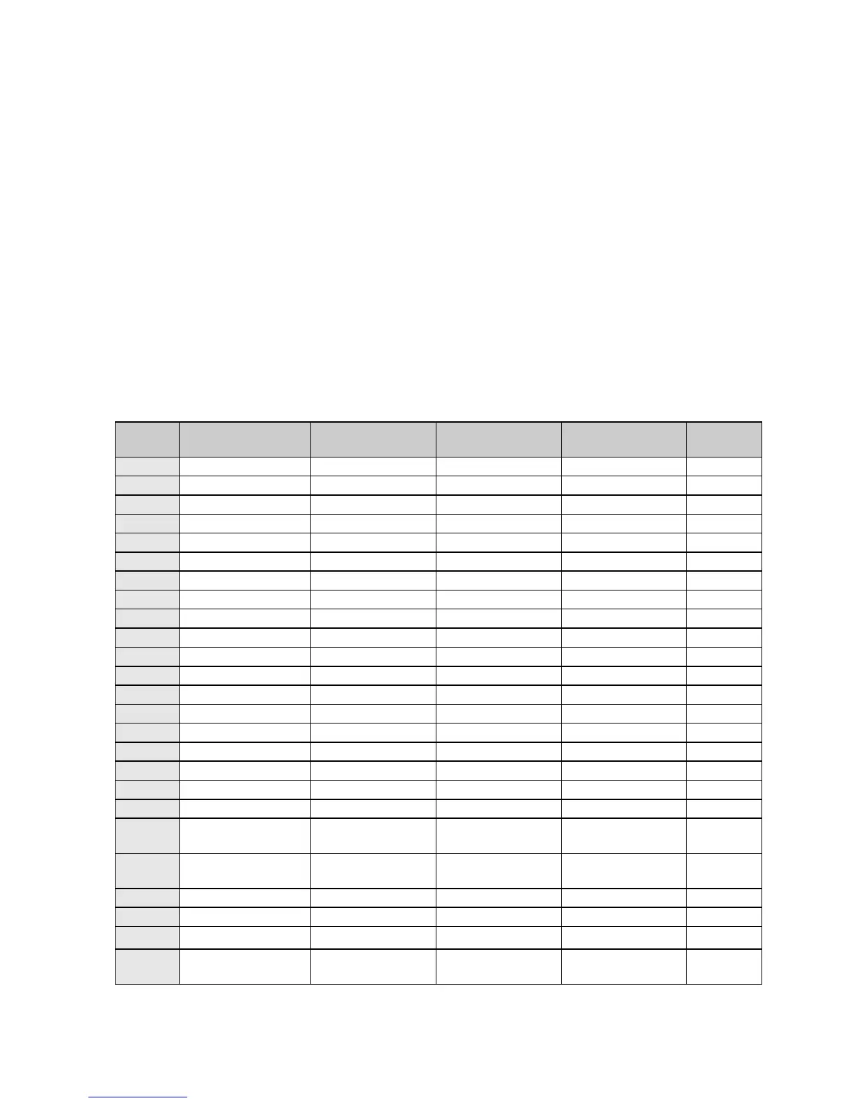
Table 2-6 shows the pin assignments for the selectable standard electrical interfaces.
Table 2-6 – Synchronous Serial Data Interface Connector Pinout (J11)
Aux RS-232
Transmit/Receive
Aux RS-232
Transmit/Receive
Aux RS-232
Transmit/Receive
Aux RS-232
Transmit/Receive