Maintenance M7/M7L/M7LT Modular Satellite Modem
2-16 M7/M7L/M7LT - Rev. 0.05
2.3.8.4.3. Dual G.703/E1 Overhead Channel Connection (J20)
The G7 interface offers access to the ESC overhead data is on an auxiliary connector located on the
rear panel, a 9-pin female “D” sub connector J20. The pin-out of this connector is determined by the
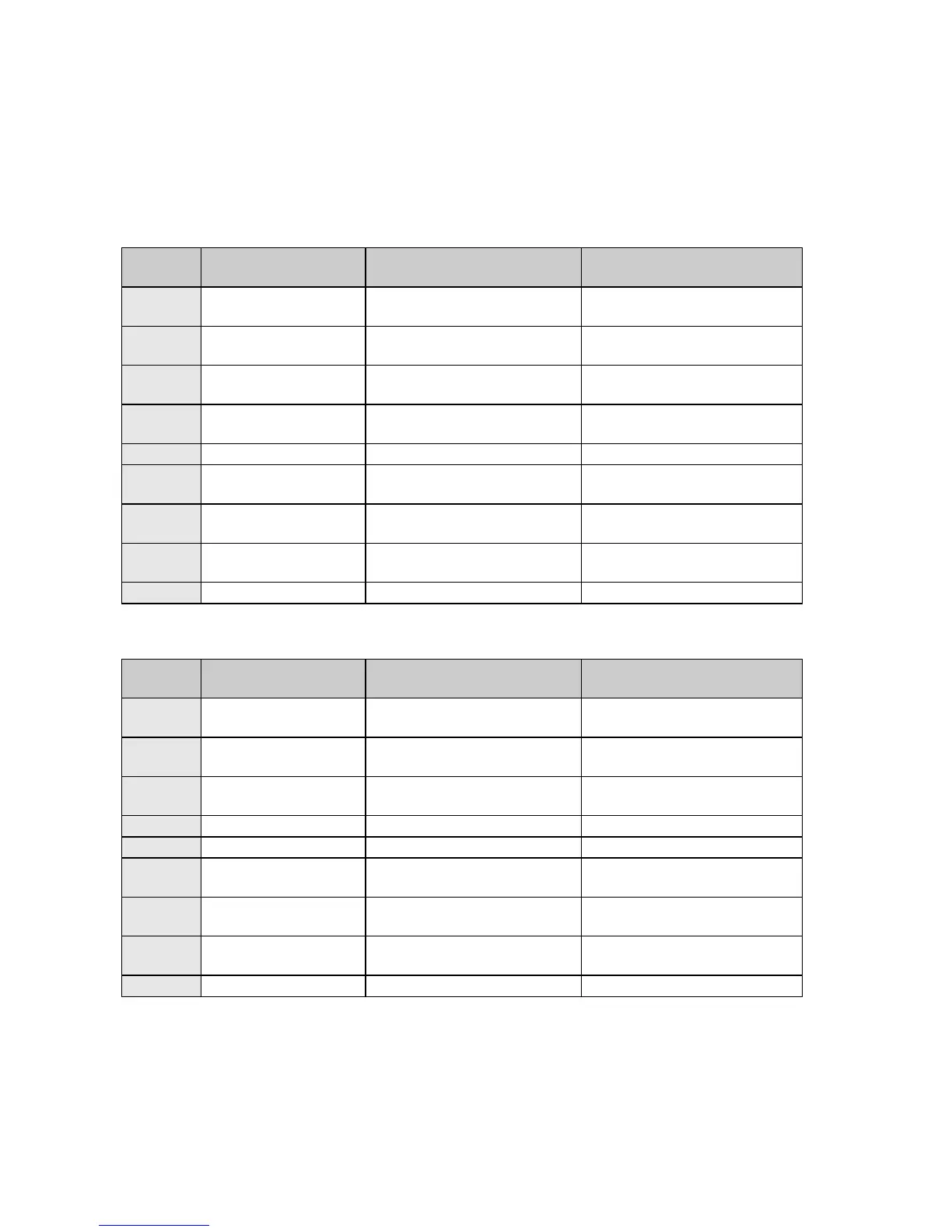
selected multiplexer mode. The pinout for the overhead connector when configured for RS-232 is
shown in Table 2-15 and when configured for RS-485 is shown in Table 2-16.
Table 2-15 - Overhead Interface - RS-232 (J20)
RS-232 Advanced/Custom
Mode Connection (sync)
RS-232 Advanced/Custom
Mode Connection (sync)
RS-232 Advanced/Custom
Mode Connection (sync)
RS-232 Advanced/Custom
Mode Connection (sync)
RS-232 Advanced/Custom
Mode Connection (sync)
RS-232 Advanced/Custom
Mode Connection (sync)
RS-232 Advanced/Custom
Mode Connection (sync)
Table 2-16 - Overhead Interface - RS-485 (J20)
RS-485 Advanced/Custom
Mode Connection (sync)
RS-485 Advanced/Custom
Mode Connection (sync)
RS-485 Advanced/Custom
Mode Connection (sync)
RS-485 Advanced/Custom
Mode Connection (sync)
RS-485 Advanced/Custom
Mode Connection (sync)
RS-485 Advanced/Custom
Mode Connection (sync)