M7/M7L/M7LT Modular Satellite Modem Maintenance
M7/M7L/M7LT - Rev. 0.05 3-3
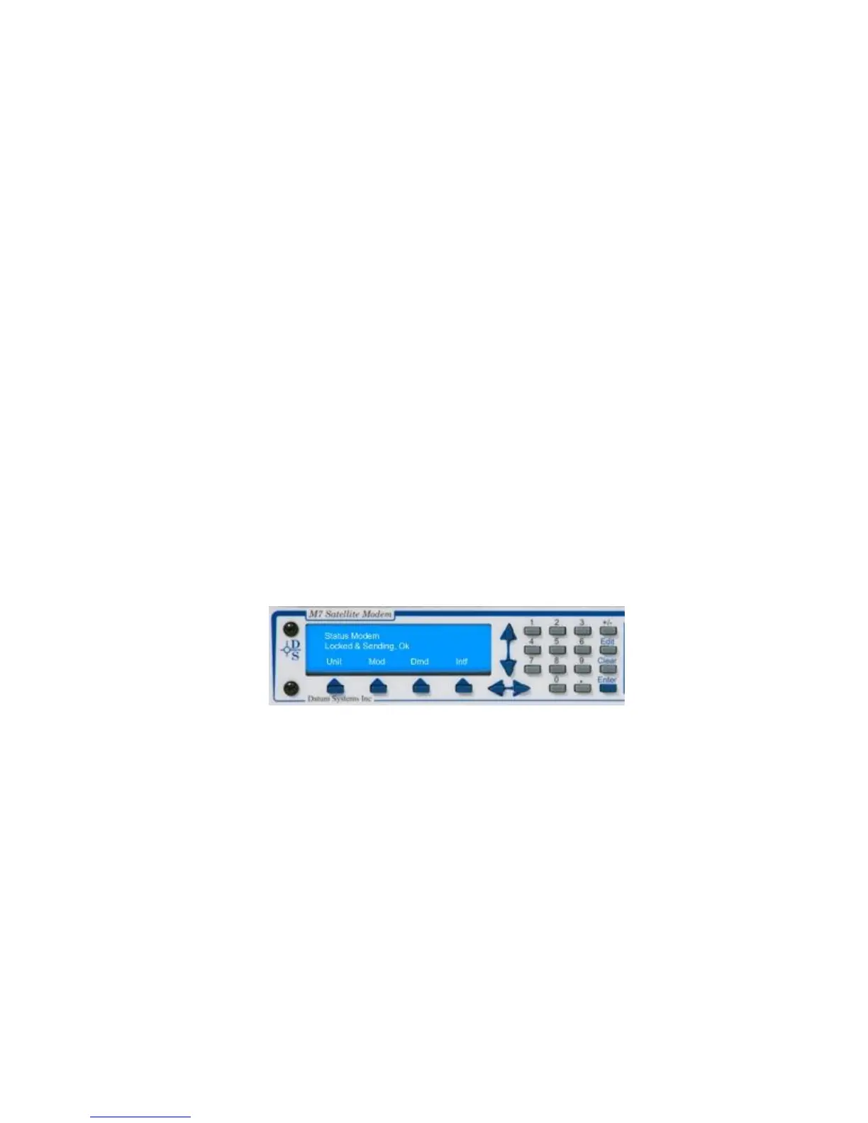
The display, shown in Figure 3-2, has four distinct areas showing current status information. The
upper left of the LCD shows the current area of use, such as “Status”, “IF”, “Data”, “Alarm” or “Test”
(for the Mod and Demod). The upper right shows the current parameter being monitored, such as
“Frequency”, “Offset” or “Bit Rate”. The middle lines show the current value of that parameter and the
bottom line will show the four legends that indicate the Modem’s functional areas. The type of the
active interface will show in the “Interface” location, for example “Sync” will be displayed when the
synchronous interface is active. At times this line may be replaced with status messages that are
longer than two lines.
NOTE: The front panel matrix functions like as three-dimensional multi-sheet spreadsheet. The
different “sheets” are selected by the buttons for Unit, Mod, Demod and Interface, while
navigation on a given sheet is accomplished using the up, down, left and right arrow keys.
3.3. Front Panel Control and Monitor Matrix
The front panel (Figure 3-2) can be used to completely control the modem setup and operating
parameters.
The modem parameters are arranged in four matrices:
“Unit” - Unit
“Mod” - Modulator
“Demod” - Demodulator
“Intf” - Interface
Each matrix represents a major functional area of modem operation (i.e. Unit, Modulator,
Demodulator, and Interface) while the columns represent groupings within those functional areas (i.e.
Status, IF, Data, Alarm and Test) and the rows represent individual parameter associated with that
function. Each matrix is 4 to 14 columns wide and up to 32 rows long as shown in the parameter
matrices example Table 3-4.
Figure 3-2 – Front Panel Matrix Navigation
Within this manual, the format used to identify a specific parameter is shown as <Function: Column
– Row>. For example, to get to the Modulator IF Level the method is to press the “Mod” key then use
the left and right arrow keys to access the “IF” column and the up and down arrow keys to arrive at
the “Level” parameter. This is shown by convention in this manual as <Mod: IF – Level>. Selection of
a specific value for the parameter will use the notation <Function: Column – Row> = value(#). The
value is descriptive and the # in parenthesis is the selection number key to press for optional
parameters, if applicable, in the direct entry mode explained below.