Maintenance M7/M7L/M7LT Modular Satellite Modem
3-32 M7/M7L/M7LT - Rev. 0.05
3.5. Front Panel Monitor and Control Parameters
Parameter matrices are available from the front panel. Within the tables following, parameters that
appear shaded are only accessible when the modem is configured to use those parameters. For
example, those parameters pertaining to the AUPC are only available when the AUPC is enabled,
and those pertaining to the Reed-Solomon Codec will appear only if the Reed-Solomon Codec is
installed and enabled. There may also be some parameters or parameter sections that will be a future
option and will be identified as such within each detailed parameter matrix table.
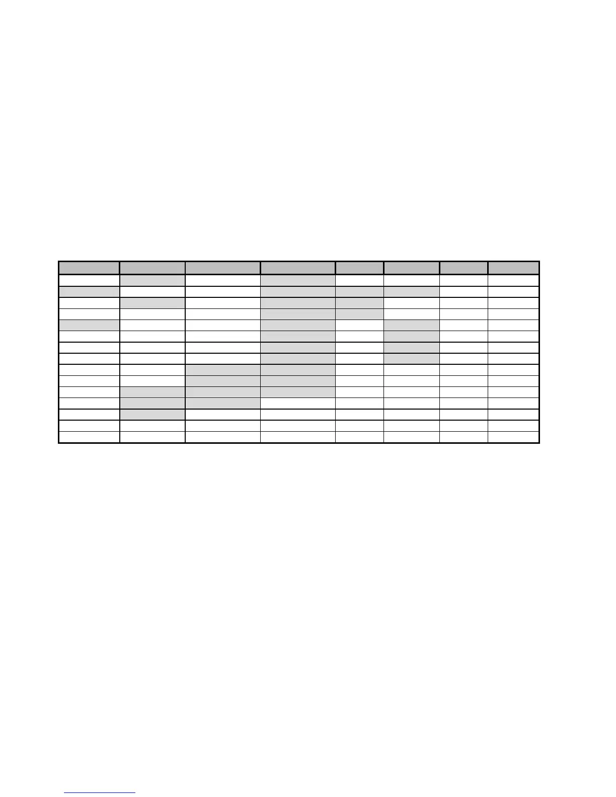
In the example of the M7 Modulator Parameter Matrix (Table 3-4) the top gray row represents column
headers, which are shown on the LCD display in the upper left. Items below the header are row
parameter names shown in the upper right of the LCD. Columns are navigated using the left and right
arrow keys while rows are navigated using the up and down arrow keys. All other parameter matrices
navigate in the same manner.
Table 3-4 - M7 Front Panel Parameter Matrix – Modulator Sheet
The tables below are organized with general “Rules of Thumb” which aid navigation.
1. The “Status” columns are generally read only, providing status on specific areas of modem
operation.
2. The Modulator and Demodulator matrixes use common column designations. A current
parameter in one area can be immediately accessed in the other by pressing the appropriate
“Mod” or “Dem” button. For example when viewing the Mod Bit Rate, the Demod Bit Rate is
accessed by simply pressing the “Dem” button.
3. The “Alarm” columns existing in all four matrixes and represents the disposition of alarm
information from that source. Therefore the <Demod: Alarm – CXR Lock> sets the
disposition of the Demodulator Carrier Lock Alarm as either None, to Alarm Relay A, to
Alarm Relay B, or to Alarm Relay A & B.
4. The “Test” columns existing in all four matrixes and represents the control and display of test
information for that area. The top entries in the Test column contain tests which can be
enabled or disabled if available. The lower rows represent measurements of parameters and
are read only. Active tests enabled in these columns generate flashing “Test” LED lamps in
appropriate areas.
NOTE: Word spelling is purposely truncated to fit in available LCD display window.
Other columns may be added by options added to the modem or software.
Redundancy parameters are only shown when connected to another unit in redundancy
mode.