Maintenance M7/M7L/M7LT Modular Satellite Modem
3-102 M7/M7L/M7LT - Rev. 0.05
Sets the address of the Send MCC
port
Sets the address of the Rcv MCC
port
3.10.1. AUPC Remote Mode
The AUPC Remote function requires at least a 500 baud data channel between the sites in order to
operate. This data channel can either be external to the modem, provided by an external multiplexer,
a telephone line modem, or provided by the internal modem control channel (MCC) when enabled.
The normal method for setting up AUPC Remote over a PtP link is to use the built in MCC to provide
the necessary communications link.
NOTE: When using an interface other than an IP interface, the “Custom” or “Advanced” Multiplexer
mode MUST be selected to provide a channel for AUPC Remote operation from the IBS
multiplexer option.
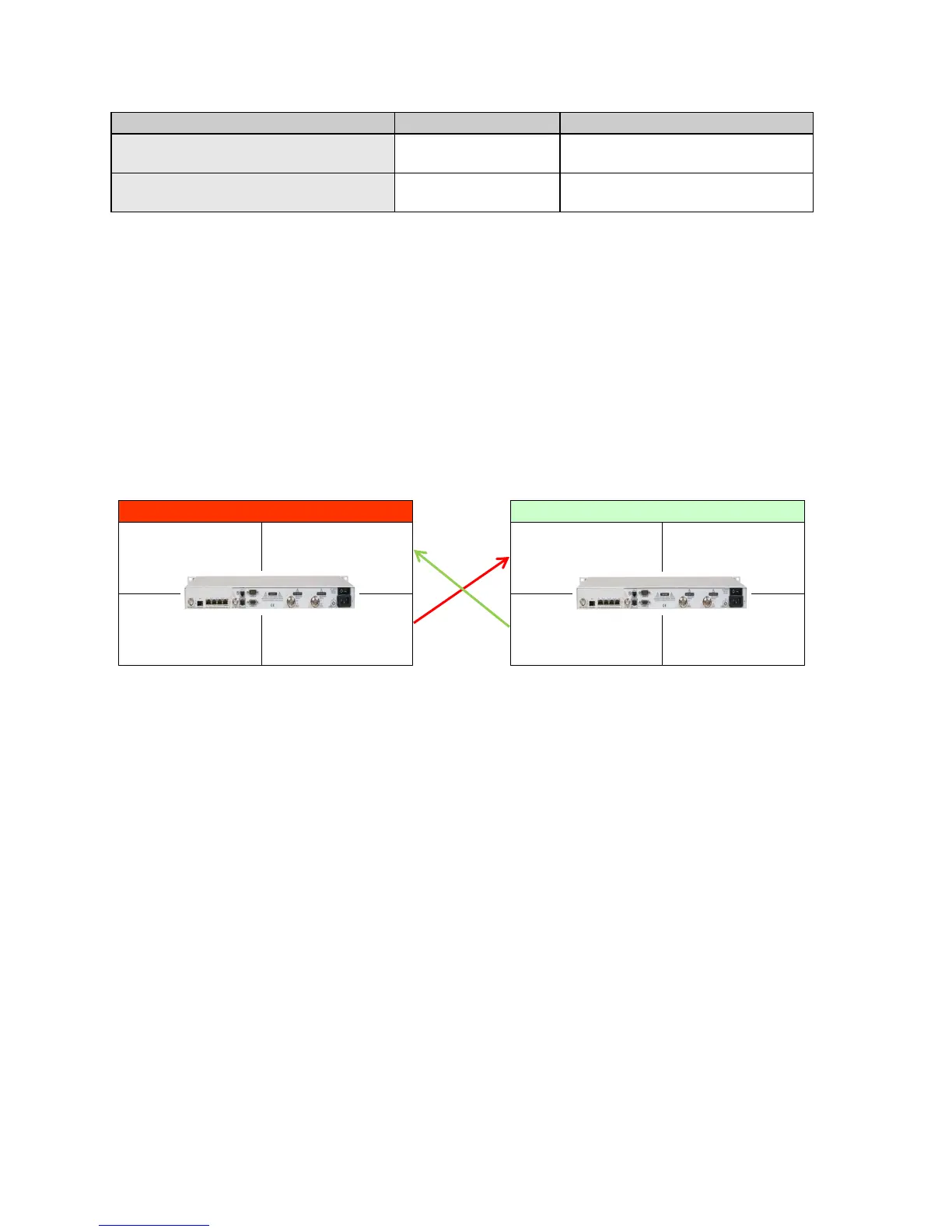
Figure 3-52 shows a PtP link between Site 1 and Site 2 with both modems set to monitor the distant
end Eb/No performance and adjust the local transmit power to maintain a set Eb/No level.
Figure 3-52 – AUPC Remote Enabled Network
3.10.1.1. AUPC Remote Mode Setup Guide
Assume a working link between Site 1 and Site 2 without any active modem control channels or
AUPC enabled and a desired link performance of 7.0 dB Eb/No.
NOTE: AUPC Remote can be enabled in a single direction or in both directions as required. When
operating AUPC Remote in a single direction, the MCC must be enabled in only the direction
necessary to return Eb/No information to the controlled transmit modem.
3.10.1.1.1. Site 2 AUPC Setup
1. Set the <Intf: MCC Mode> parameter to “Full Access”.
2. Set the <Intf: MCC Send Rate Limit> parameter to “0.500 kbps” or higher.
3. Set the <Intf: MCC Send Address> and <Intf: MCC Rcv Address> parameters to “1” for
this example. The setting of this address can be any address between 1 and 254 but must
match the <Demod: IF AUPC Remote MCC Address> setting of the modem at Site A.
4. Set the <Demod: IF AUPC Remote Path> to “Out MCC Port”.
5. Set the <Demod: IF AUPC Remote MCC Address> to “2” for this example. The setting of
this address can be any address between 1 and 254 but must match the <Intf: MCC Send
Address> and <Intf: MCC Rcv Address> parameter settings of the modem at Site A.
6. Set the <Mod: IF AUPC Mode> to “Enabled”.
7. Set the < Mod: IF - AUPC Eb/No> to the desired value, e.g. 7.0 dB.
8. Set the < Mod: IF - AUPC Max Level> parameter to the desired level. Determine the value
for this parameter by calculating the maximum power that is allowed to prevent the link from
Dmd
IF AUPC Remote Path = Enabled
IF AUPC Remote MCC Address = 1
IF AUPC Remote Path = Out MCC Port
Mod
IF AUPC Mode = Enabled
Intf
MCC Send Address = 2
MCC Rcv Address = 2
Unit
Modem 1
Dmd
IF AUPC Remote Path = Enabled
IF AUPC Remote MCC Address = 2
IF AUPC Remote Path = Out MCC Port
Mod
IF AUPC Mode = Enabled
Intf
MCC Send Address = 1
MCC Rcv Address = 1
Unit
Modem 2