Operation M7/M7L/M7LT Modular Satellite Modem
1-10 M7/M7L/M7LT - Rev. 0.05
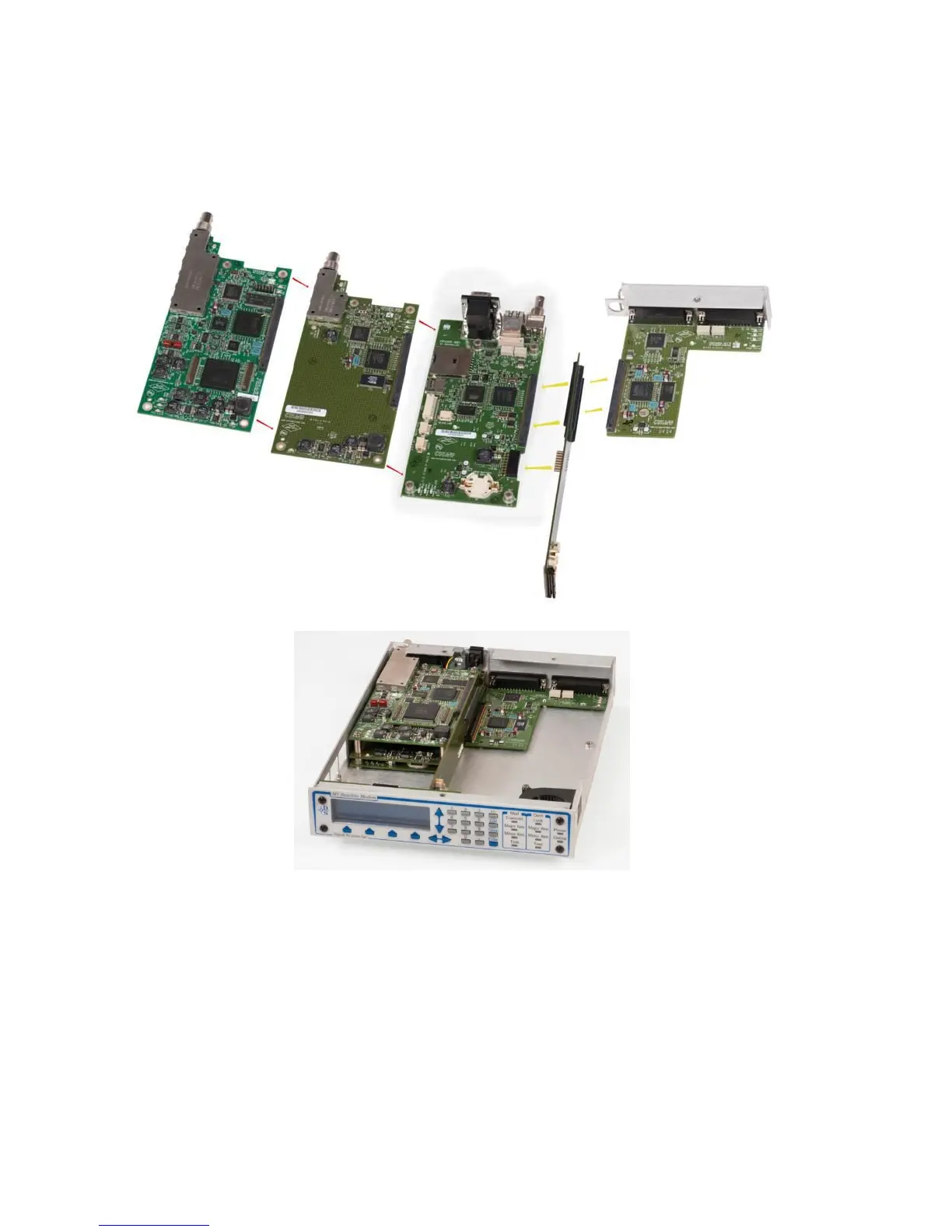
1.4. M7 Modem Assemblies
The M7 consists of four (4) main functional elements arranged on electronic printed circuit
assemblies, as shown in Figure 1-7. A simplified block diagram of the M7 is shown in Figure 1-8.
Figure 1-7 – M7 Modem Assemblies (shown with standard serial interface)
The modem assembly consists of the following major assemblies:
The M7 digital PSK/QAM modulator with carrier generation in the 50 to 180 MHz range for
standard modem, or 950 to 2150 MHz in the L-Band versions.
The M7 digital PSK/QAM demodulator accepting signals in the 50 to 180 MHz range for the
standard modem or 950 to 2150 MHz in the L-Band versions. The Digital Signal Processor
Acquisition subsystem is part of the demodulator assembly.
The M7 microprocessor monitor/control subsystem.
The optional M7 Data Interfaces. The standard serial data interface assembly contains selectable
serial electrical interface types – EIA-422, EIA-232 Synchronous, EIA-232 Asynchronous, and
V.35 on an EIA-530A 25 pin “D” connector. The modem can also accept special interfaces via an
alternate or additional interface cards such as G.703, HSSI and Ethernet.