M7/M7L/M7LT Modular Satellite Modem Maintenance
M7/M7L/M7LT - Rev. 0.05 2-3
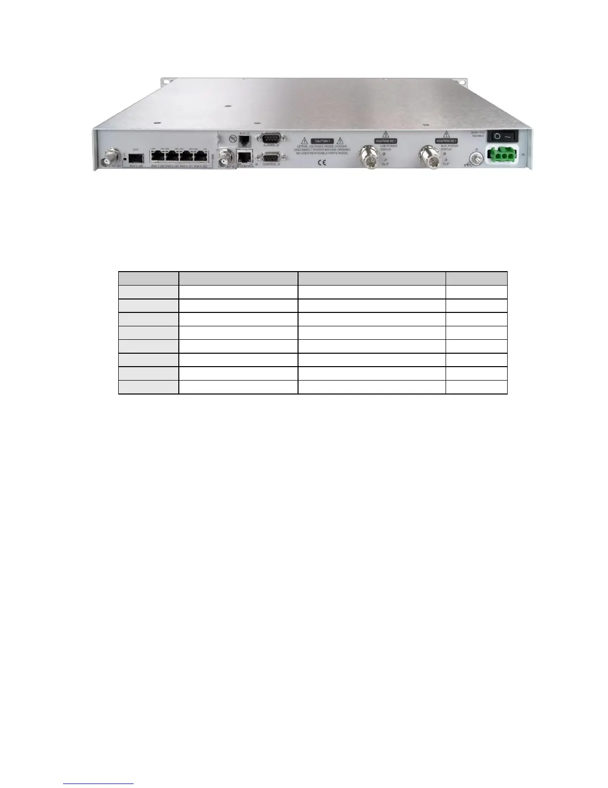
Figure 2-3 – M7LT Rear Panel with DC Prime Power Input
2.3.2. IP Control RJ45 (J4)
The RJ45 IP Control connection provides remote control of the modem via a Web Browser page or
SNMP. Refer to Table 2-1 for the pinout of the Auxiliary connector.
Table 2-1 - Remote IP Control Connector Pinout (J4)
2.3.3. Auxiliary RJ11 (J3) (Future Option)
The RJ11 auxiliary connector J3 is used for redundancy operation and contains all control signals
required for 1:1 redundancy operation.
2.3.4. EIA-485/232 Control Port - 9-pin female “D” sub connector (J5)
The modem has a command interface serial control port which can be configured for either of two
electrical interface modes of operation. Both are located on the rear panel 9-pin female “D” sub
connector J6. Connection to either the RS-232 or RS-485 is selected by connecting to the proper set
of pins as shown in Table 2-2, and setting the remote mode as applicable via the front panel control.
If a 2 wire RS-485 bus is desired, then transmit and receive RS-485 lines must be externally
connected together (1 to 8 and 6 to 9).
NOTE: RS-485 supports both 2 wire and 4 wire interfaces.