Maintenance M7/M7L/M7LT Modular Satellite Modem
2-4 M7/M7L/M7LT - Rev. 0.05
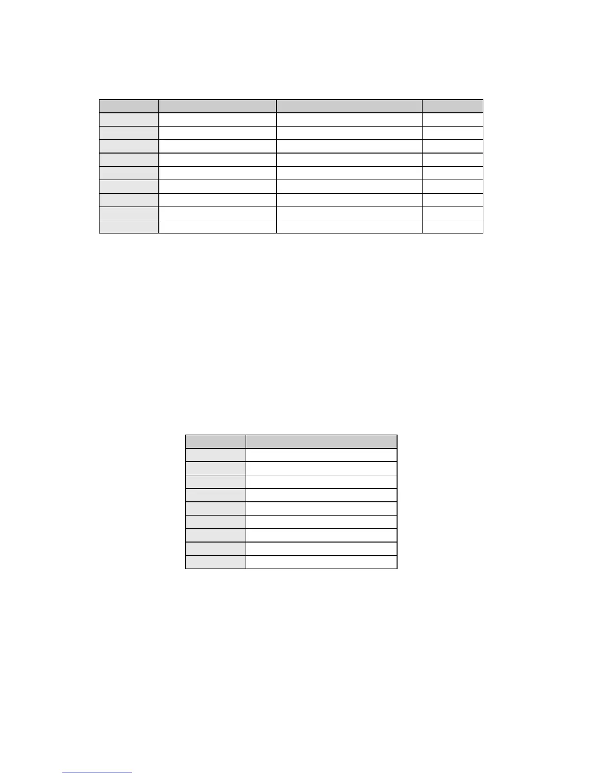
Table 2-2 - Remote Control Connector Pinout (J5)
RS–485 Transmit Data (B) +
RS-485 Transmit Data (A) -
RS-485 Receive Data (B) +
RS-485 Receive Data (A) -
Refer to Appendix C - Cabling Specifications for information on making a remote control cable.
2.3.5. Alarm Connector - 9-pin male “D” connector (J6)
The modem has two form-C dry contact alarm relays on board and an alarm connector located on the
rear panel, the 9-pin male “D” sub connector J6.
The two relays are designated “A” and “B” and the particular alarms that are summarized on each
relay are programmable from the front panel of the unit or via remote control. Connection to the A and
B relays is via the proper set of pins as shown in Table 2-3 below and programming the applicable
alarm entries via the front panel control or remote control. Non-Alarm is defined as the powered state
of the relay resulting in an alarm when power is lost.
The analog monitor output is programmable from the front panel to select Receive Eb/No, Receive
AGC voltage, or Transmit output power.
Table 2-3 - Alarm Connector Pinout (J6)
Analog Monitor Output (1kOhm)
NOTE: By convention “NO” means Normally Open, and “NC” means Normally Closed. Both
conditions are the non-powered, Alarm State.