Maintenance M7/M7L/M7LT Modular Satellite Modem
2-8 M7/M7L/M7LT - Rev. 0.05
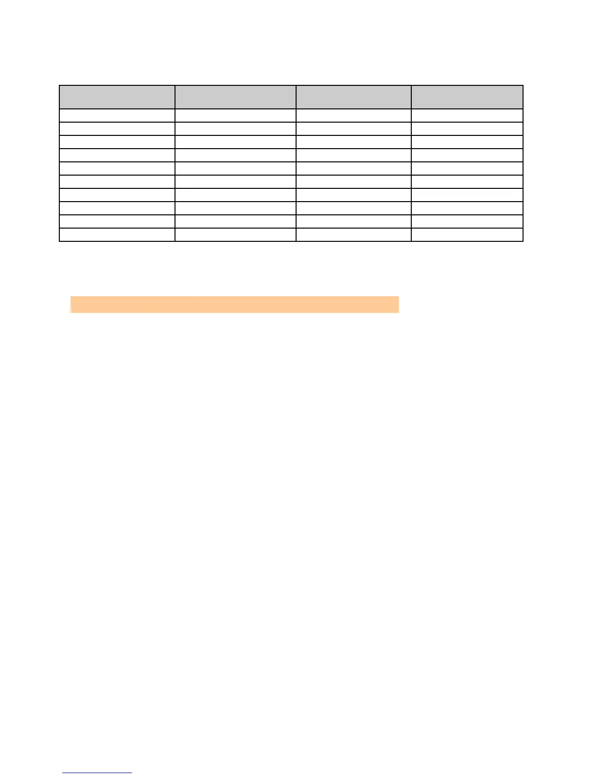
Table 2-5 – BUC power supply options
BUC Power Supply
Input Voltage
BUC Power Supply
Output Voltage
BUC power Supply
Power Rating
BUC power Supply
Max Current
NOTE: DC Power Input is isolated so it can be either positive or negative ground;
NOTE: All M7LT DC units are shipped from the factory with a five foot 3-conductor cable with mating
connector on one end that will allow connection to the main DC supply at the installation site.
CAUTION!: VERY important that the polarity needs to be wired correctly
2.3.7. The Modem External Reference Input at female BNC (J1)
The modem External Ref Input is located on a 50 female BNC J1. The 1, 5, 9 or 10 MHz input
frequency of this interface is programmable from any control interface. A sine wave input level of +10
to –15 dBm is required for normal operation. Please refer to the specifications in Appendix A