M7/M7L/M7LT Modular Satellite Modem Maintenance
M7/M7L/M7LT - Rev. 0.05 2-15
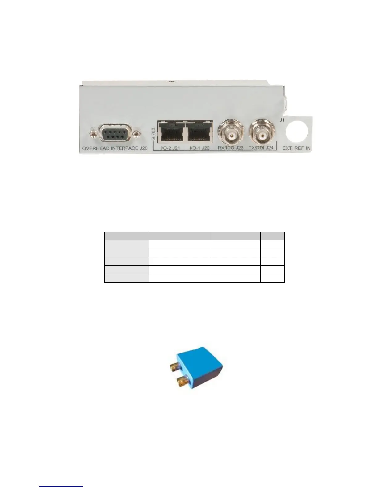
2.3.8.4. Dual G.703/E1 Interface (G7)
The G7 interface has five (5) user interface connectors on the rear panel (Figure 2-11) of the optional
card. Refer to Table 2-14 for the connector type, signal names, and connector pinout.
Figure 2-11 – G7 - Dual G.703/E1 Interface Rear Panel
2.3.8.4.1. Dual G.703/E1 120 ohm Balanced Interface
The G7 interface offers dual G.703/E1 balanced interfaces presented on two (2) RJ48c connectors –
(Port 1) and (Port 2). The pinout for the two connectors are shown in Table 2-14
Table 2-14 - Port 1 (J22) & Port 2 (J21) Connector – 120 ohm Balanced Pinout (RJ48c)
2.3.8.4.2. Dual G.703/E1 75 ohm Unbalanced
The G7 interface offers dual G.703/E1 unbalanced interfaces presented in two ways. For Port 1, two
(2) BNC connectors (J23 and J24) provide direct for the data interface. For Port 2, a connector
adapter must be used to convert the unbalanced interface signals on the RJ45 (J22) to unbalanced
(75ohm, BNC). This adapter is available from Datum Systems and shown in Figure 2-12.
Figure 2-12 – RJ45 to BNC adapter