M7/M7L/M7LT Modular Satellite Modem Maintenance
M7/M7L/M7LT - Rev. 0.05 3-93
The menu setting for the E7 interface in the hub M7 multi-demod #2 and #3 would be:
<Intf: Rcv WAN Mode = Hub Bridge PTMP>
<Intf: I/O Port 1 Mode = Dmd Output I/O>
<Intf: I/O Port 4 Mode = Dmd Input I/O>
The menu setting for the E7 interface in the M7s at the distant end of the links would be:
<Intf: Send WAN Mode = Remote Bridge PTMP>
<Intf: Rcv WAN Mode = Remote Bridge PTMP>
The physical connections shown in Figure 3-47 are specific to this example and are dependent on the
number of sites in the network. This example is a very simple PtMP example and a more complex
network with more user ports and modems would require careful attention to the E7 interface
configuration within the hub M7s.
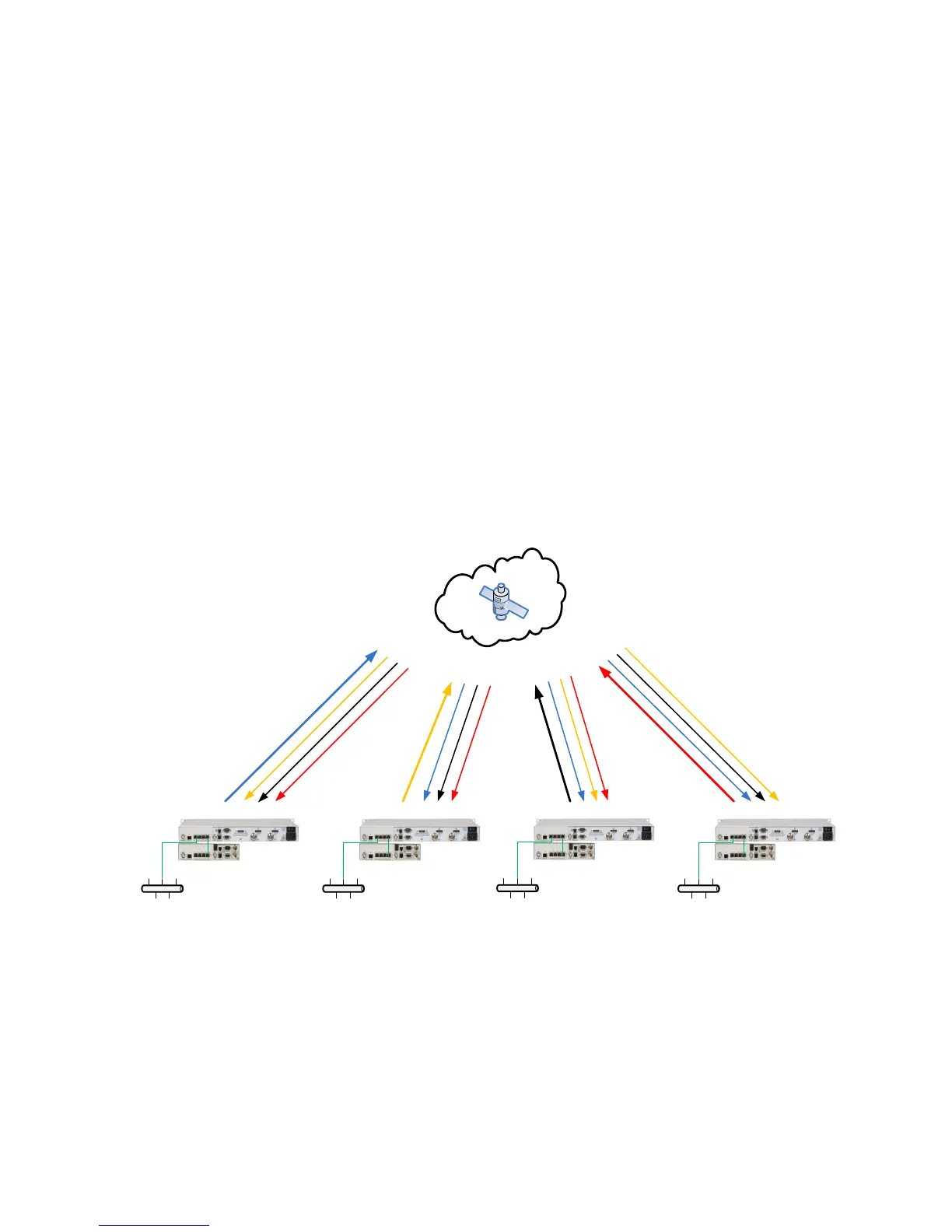
3.8.2.4.3. Mesh Satellite Network
Figure 3-48 shows a typical four (4) site MESH satellite network that could be used for connecting
multiple remote locations with a single satellite hop. In a PtMP network, multiple remote sites can be
connected but all of the traffic would need to transit the Hub location which would cause two (2)
satellite hops. Real time applications operate better with less delay and the difference between a
PtMP network double hop connection and a Mesh single hop connection can make the difference for
acceptable user experience.
Figure 3-48 – Four site Mesh network example
Configuration of the hub M7s with E7 interface is critical to proper network operation. The physical
cable connections for a PtMP Hub and single remote example are shown in Figure 3-47.
M7LD Dual-Demod
M7LT Terminal
M7LD Dual-Demod
M7LT Terminal
M7LD Dual-Demod
M7LT Terminal
M7LD Dual-Demod
M7LT Terminal
Site 4
Site
3
Site
2
Site 1