M7/M7L/M7LT Modular Satellite Modem Maintenance
M7/M7L/M7LT - Rev. 0.05 3-111
The modulator burst mode is controlled by the interface RTS/CTS and data flag signals. The
sequence of events for the burst mode is as follows:
1. The RTS from the DTE device is normally active. The idle character from the DTE is a
continuous Mark condition. The modulator output carrier is off in this idle state.
2. The modulator responds to the DTE device when ready to transmit by activating the CTS
signal.
3. Any time after the CTS is received by the DTE, the DTE starts transmitting flags and/or data.
The first non–SDLC/HDLC flag character received by the modulator is the start of
transmission signal, causing the modem to generate a preamble and initiate the “Carrier ON”
command. Transmission continues with data bytes placed after the preamble.
4. The next SDLC/HDLC flag received by the modulator is the end of transmission signal.
5. When the closing flag is detected by the modulator, it drops the CTS indicating that a new
data message cannot be started. When the last data bit is sent, the modulator will reassert
the CTS signal, and turn the carrier OFF.
3.14. Built-in 1:1 Redundancy Mode Operation (Future Option)
The modem has a built-in 1:1 redundancy mode that allows two modems to be connected together
sharing connections, but with only one unit “on-line”. The built-in software provides automatic back-up
protection should the on-line unit indicate a failure by switching to a functioning off-line unit.
NOTE: The two modems must be the same model number and type, and should be at the same
firmware revision for proper redundant operation.
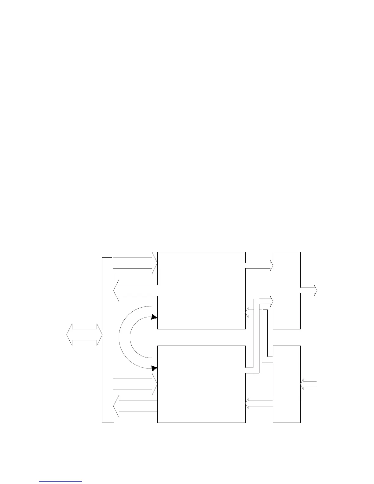
A diagram of the connections required for 1:1 redundancy is shown in the Figure 3-55 below.
Modem A
Modem B
Aux Xmt
Aux Rcv
Aux Xmt
Aux Rcv
Transmit
IF
Combiner
Receive IF
Splitter
Data "Y" Cable Paired Modems
Station IF
Equipment
Xmt IF
Xmt IF
Rcv IF
Rcv IF
Figure 3-55 – M7 Connections for 1:1 Redundancy