Maintenance M7/M7L/M7LT Modular Satellite Modem
2-18 M7/M7L/M7LT - Rev. 0.05
NOTE: The FIFO External Clock pins are an input to the modem. An input at the receive data rate
can be used to clock data out of the demodulator FIFO buffer. An input at the transmit data
rate can be used to provide a transmit send timing clock which the modem will phase locked
to (if within acceptable range). The send timing signal is still an output from the modem, but in
this case will be at the input signal rate. Both functions can be used simultaneously if the
transmit and receive data rates are the same.
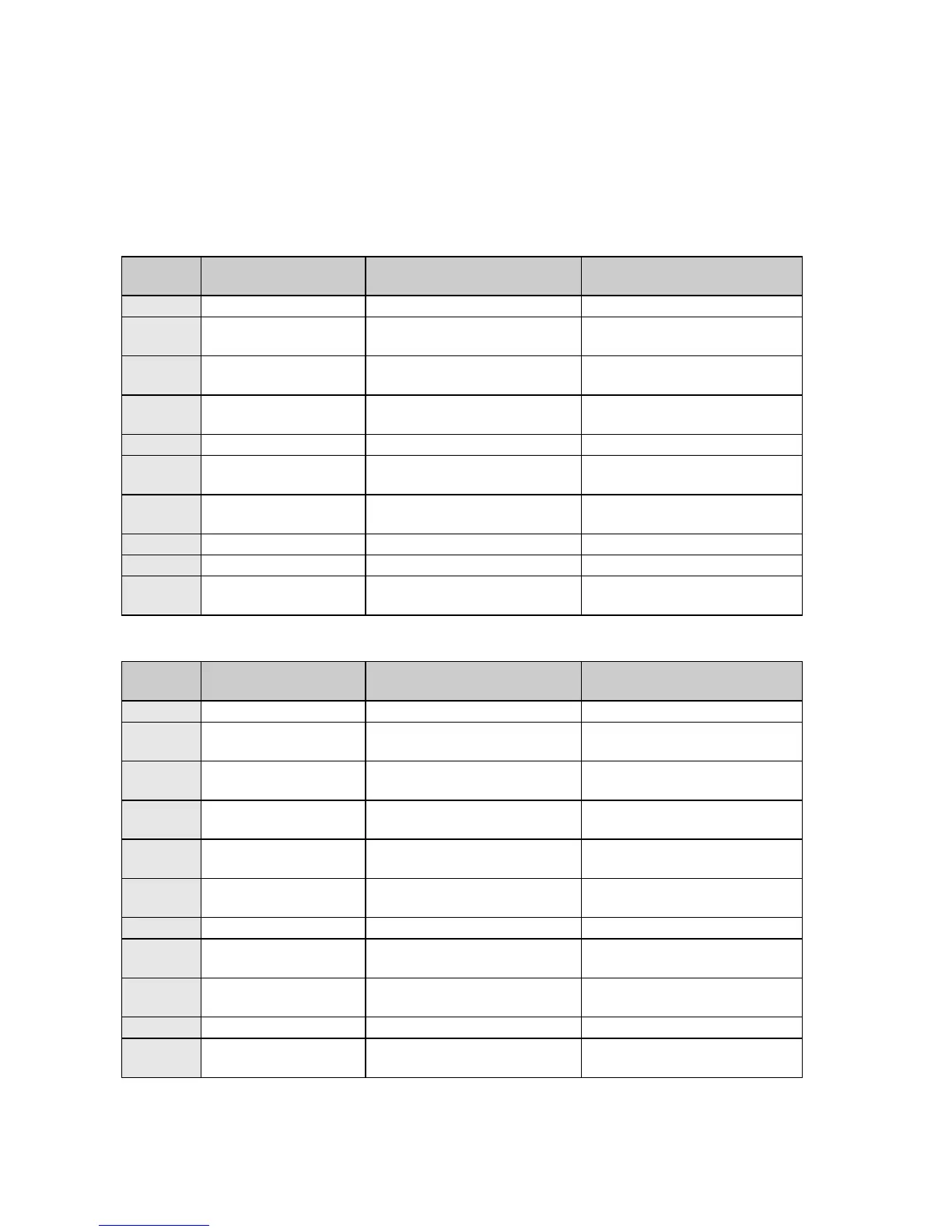
Table 2-17 – M7 Overhead Channel - IBS Standard Mux - RS-232 (J25)
RS-232 Standard Mode
Connection (synchronous)
RS-232 Standard Mode
Connection (synchronous)
RS-232 Standard Mode
Connection (synchronous)
RS-232 Standard Mode
Connection (synchronous)
Primary Interface
External Clock+ (B)
FIFO External Clock input ‘+’
or ‘B’ line. RS422 level
Primary Interface
External Clock- (A)
FIFO External Clock input ‘-‘ or
‘A’ line. RS422 level
Table 2-18 – M7 Overhead Channel - IBS Standard Mux - RS-485 (J25)
RS-485 Standard Mode
Connection (synchronous)
RS-485 Standard Mode
Connection (synchronous)
RS-485 Standard Mode
Connection (synchronous)
RS-485 Standard Mode
Connection (synchronous)
RS-485 Standard Mode
Connection (synchronous)
RS-485 Standard Mode
Connection (synchronous)
Primary Interface
External Clock+ (B)
FIFO External Clock input ‘+’
or ‘B’ line. RS422 level
Primary Interface
External Clock- (A)
FIFO External Clock input ‘-‘ or
‘A’ line. RS422 level