DriveRack™ User Manual
2
Section 1
DriveRack
™
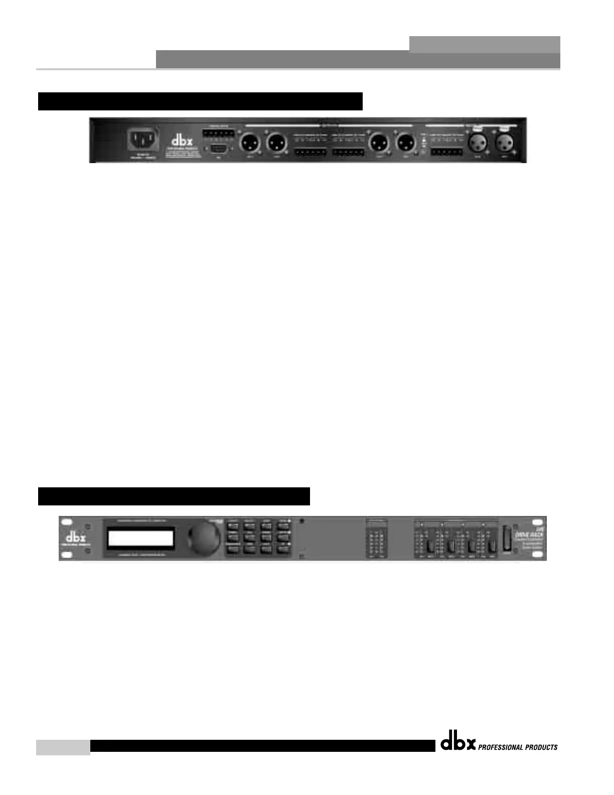
IEC Power Cord Receptacle
The 240 comes with an universal power supply that will accept voltages ranging from 100V-
240V at frequencies from 50Hz-60Hz. An IEC cord is included.
Switch Closure Connection
This Euroblock-type connector is used to interface the 240 with wall-mount zone control sys-
tem switches. For more information regarding the switch closure connection and its applica-
tions, please see the Utilities sections.
PC Connection
This DB-9 type connection is used to send and receive information to and from the GUI inter-
face.
Outputs 1-4
The output section of the 240 DriveRack™ offers four electronically balanced XLR and two
Euroblock connectors. Note: The XLRs are wired in parallel with the Euroblock connectors.
Inputs 1-2
The input section of the 240 DriveRack™ offers two electronically balanced XLR and Euroblock
connectors. Note: Do not use both input types (XLR and Euroblock) simultaneously.
Ground Lift Switch
The ground lift switch lifts the pin 1 chassis ground of both input XLR connectors as well as the
chassis ground connector of the euroblock input connector.
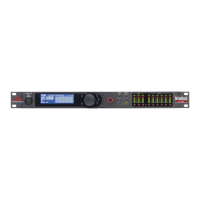
LCD Display
The backlit LCD display of the 240 DriveRack™ provides the user with all of the vital process-
ing information of the DriveRack™ including: signal routing, configuration modes and effect
block editing. The display will also notify the user if any internal clipping is taking place with-
in the unit. The following messages will appear: CLIP: Pre Xover (clipping prior to the
crossover section), CLIP: Post Xover (clipping past the crossover section), and CLIP: Pre/Post
(clipping in both sections).
Data Wheel
The data wheel of the 240 DriveRack™ is used to scroll through the program menu and edit
parameters values. Pressing the Data wheel will allow you to instantly move to other parame-
ters.
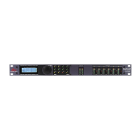
1.2 Front Panel (240)
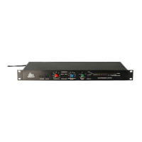
1.1 Rear Panel Connections (240)