DriveRack™ User Manual
4
Section 1
DriveRack
™
Outputs 1-4
The output section of the 240 DriveRack™ offers four electronically balanced XLR and two
Euroblock connectors. Note: The XLRs are wired in parallel with the Euroblock connectors.
Inputs 1-2
The input section of the 240 DriveRack™ offers two electronically balanced XLR and Euroblock
connectors. Note: The XLR connectors are wired in parallel with the Euroblock. Note: Do not
use both input types (XLR and Euroblock) simultaneously.
Ground Lift Switch
The ground lift switch lifts the pin 1 chassis ground of both XLR connectors as well as the chas-
sis ground connector of the euroblock input connector.
PC Connection
This DB-9 type connection is used to send and receive information to and from the computer
running the DriveWare™ software. Note: this connection is parallel with the DB-9 connection
on the rear panel.
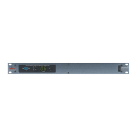
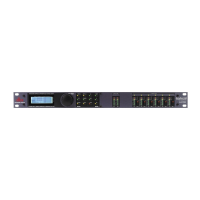
Program Up and Down
These program up and down buttons are used to scroll through the program menu of the 241.
Program Display
This program display is used to indicate the currently selected program of the 241.
Clip note: In the event that there is internal clipping within the signal path of the 241, “CL”
(indicating clipping) will briefly appear.
Load Button
The load button is used to load the currently selected program number which is flashing in the
program display.
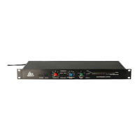
1.4 Front Panel (241)