For those of you that wish to jump right in, the following information has been provided to act
as a quick start guide for optimizing performance of the 240/241 DriveRack units.
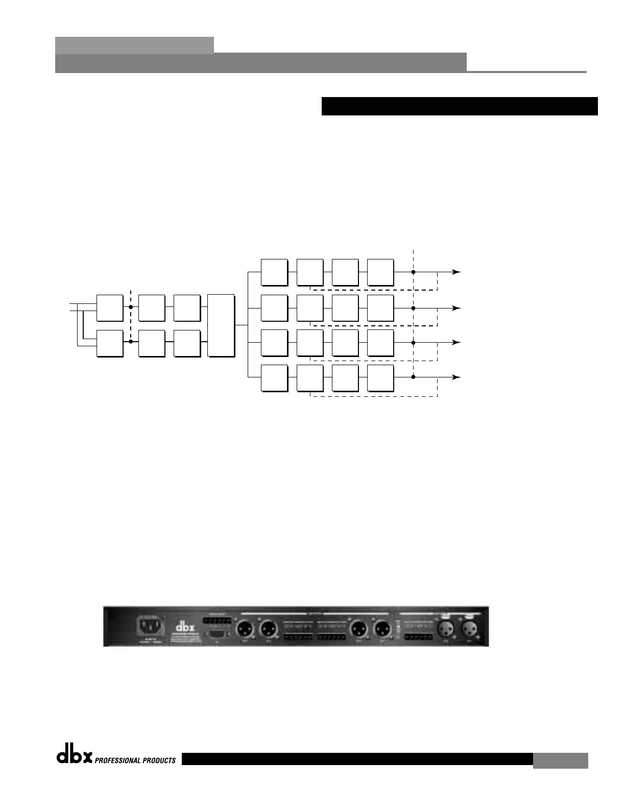
Signal Path Block Diagram
The following diagram shows the logical and intuitive signal path of the input, effect modules,
and output of the 240 and 241 DriveRack units.
• When setting up the 240/241 DriveRack™, make connections as follows:
•Make connections prior to powering the unit up.
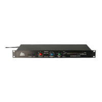
• Connect the output from the sending device (mixer) to any one of the two XLR or
Euroblock input shown below. Note: XLR and Euroblock connectors are wired in
parallel.
• Make output connections from any one of the four output XLR or Euroblock connec-
tors shown below to the input of the selected power amp.
• If application requires, make switch closure connections.
The DriveRack can power up with the outputs muted, this will help ensure that damage
can not be done to the speakers or other subsequent equipment.