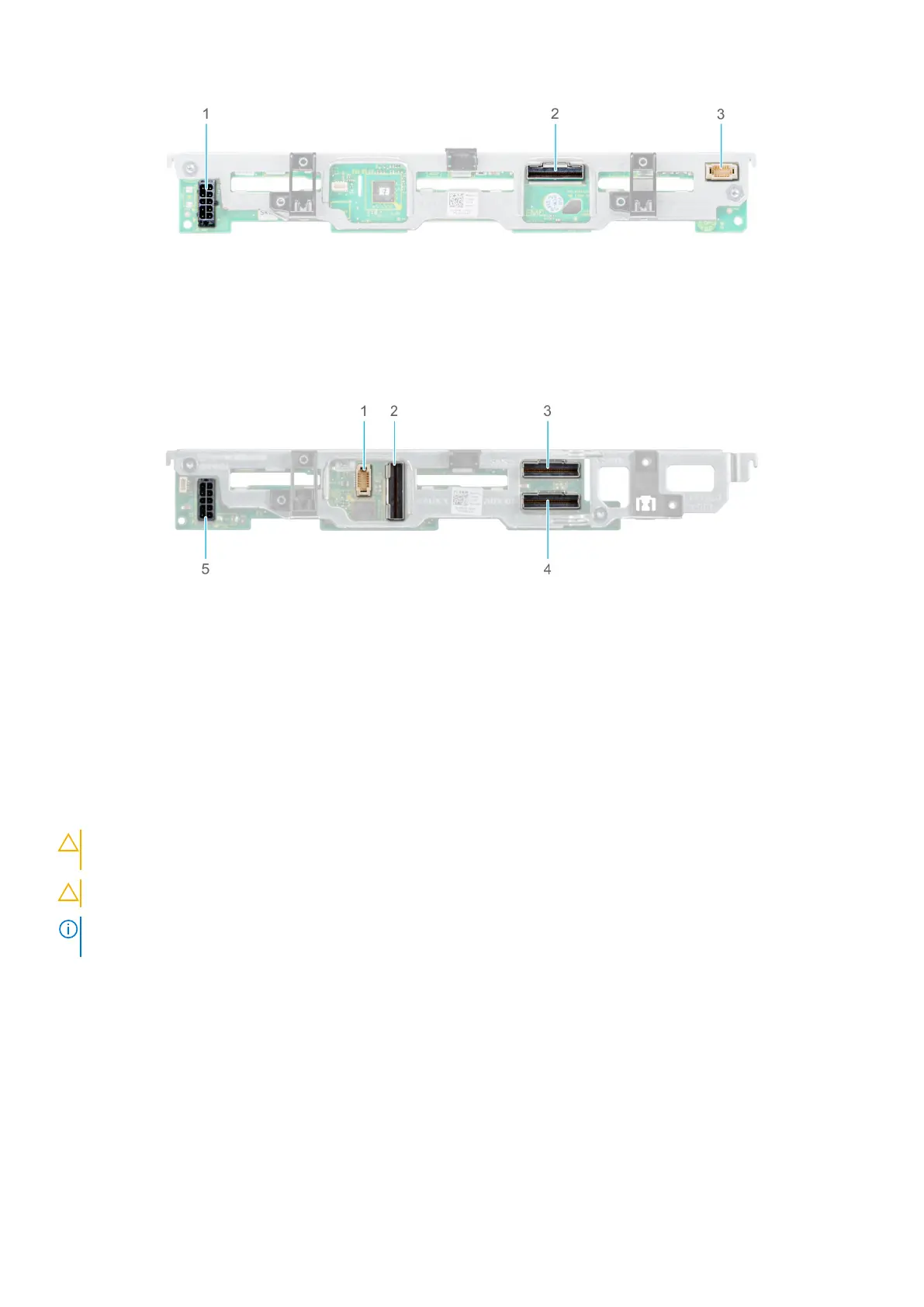
Figure 27. 6 x 2.5-inch SAS/SATA backplane
1. Power cable connector
2. SAS/SATA connector
3. Signal cable connector
Figure 28. 4 x 2.5-inch universal backplane
1. Signal cable connector
2. AUX 1 cable connector
3. SAS/SATA connector
4. AUX 0 cable connector
5. Power cable connector
Removing drive backplane
Prerequisites
CAUTION:
To prevent damage to the drives and the drive backplane, you must remove the drives from the
system before removing the drive backplane. For more information, see Removing a drive carrier.
CAUTION: Temporarily label drives before you remove the drive so that you can replace them in the same slots.
NOTE: Observe the routing of the cable as you remove it from the sled. Route the cable properly when you replace it, to
prevent the cable from being pinched or crimped.
1. Follow the safety guidelines listed in Safety Instructions.
2. Follow the procedure listed in Before working inside your sled.
3. Disconnect the cables connected to the backplane.
4. Remove the drives.
Steps
1. Hold the drive backplane by the edges and lift it upwards to disengage the backplane from the guide pins.
2. Lift the backplane out of the sled.
30
Installing and removing system components

 Loading...


