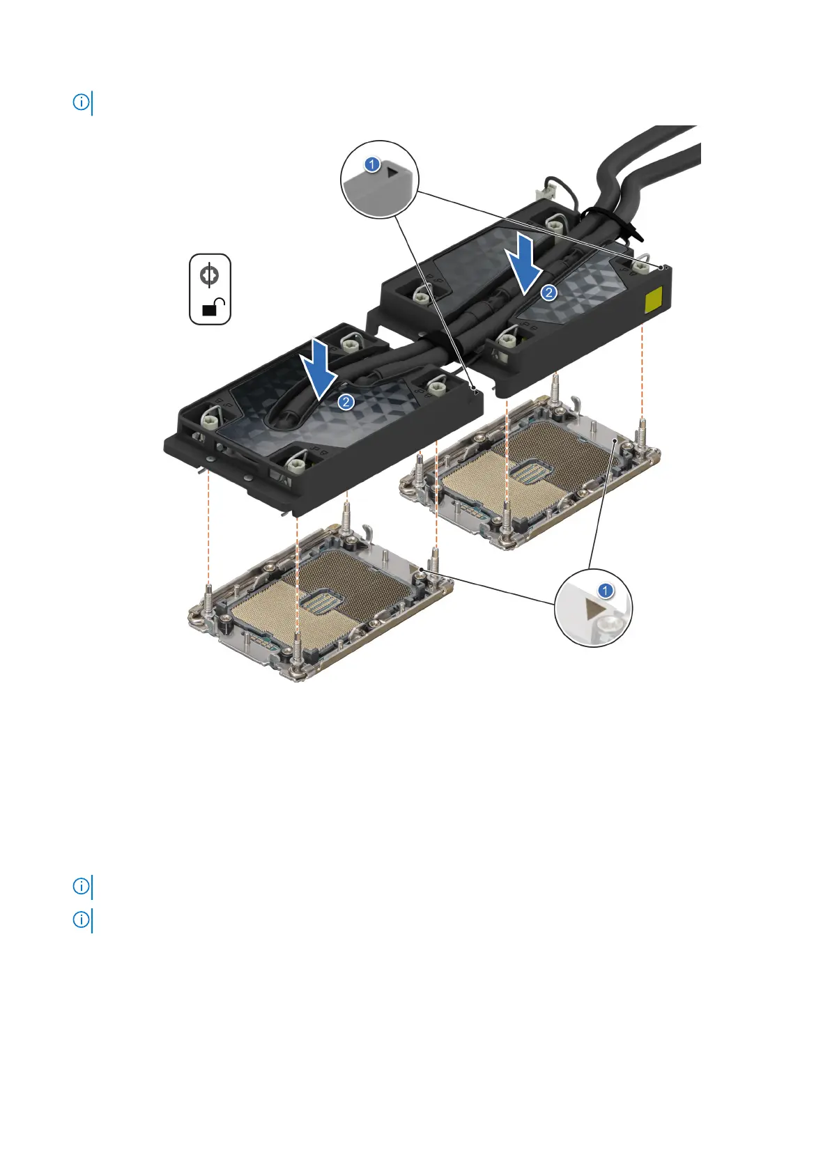
NOTE: The numbers on the image do not depict the exact steps. The numbers are for representation of sequence.
Figure 87. Installing the processor and liquid cooling cold plate
3. Set the Anti-Tilt wires to the locked position (outward position), and then using the Torx T30 screwdriver, tighten the
captive nuts on each cold plate, one at a time, in the order below:
a. Tighten the first nut.
b. Tighten the screw diagonally opposite to the nut you tighten first.
c. Repeat the procedure for the remaining two nuts.
4. Place the rubber tubes down into the cutout features on the rear wall.
5. Reconnect the leak sensor connector cable back to the system board.
NOTE: It is critical to ensure the sensor cable is connected.
NOTE: The numbers on the image do not depict the exact steps. The numbers are for representation of sequence.
Installing and removing system components 111





 To Next Page