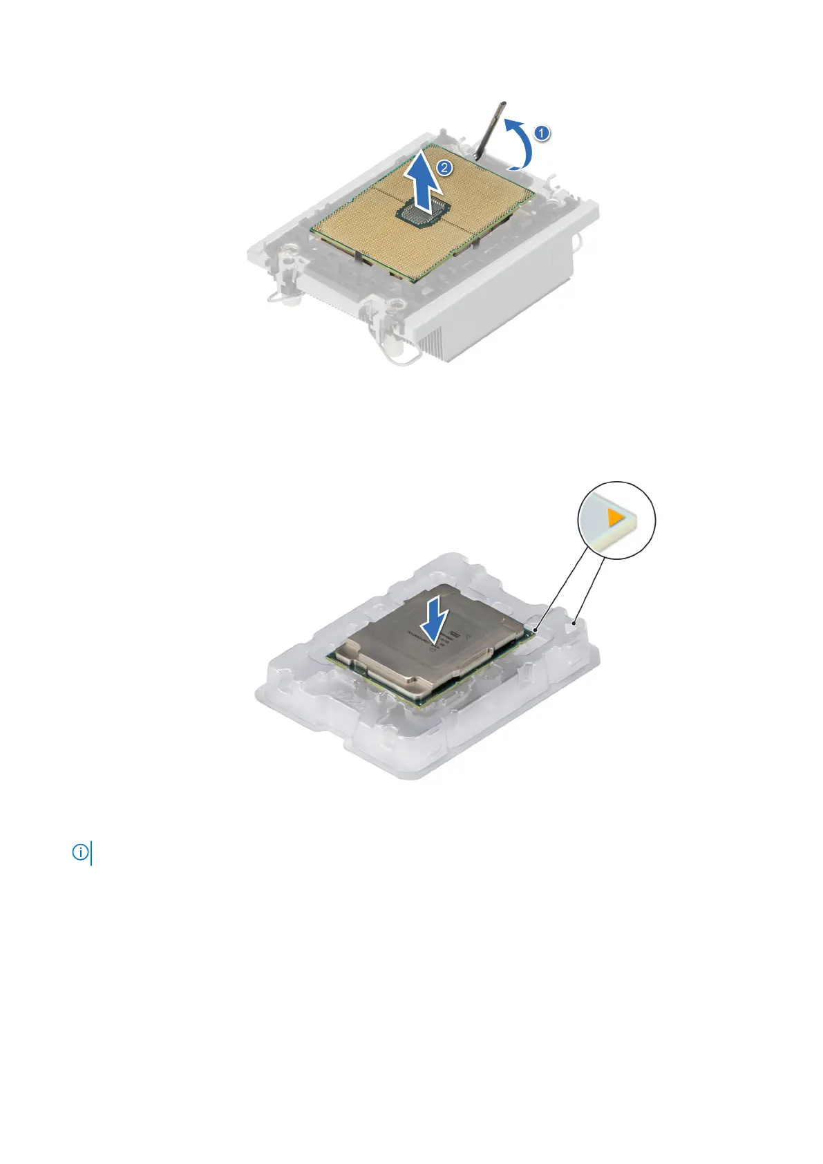
Figure 65. Lift the TIM break lever
Figure 66. Aligning pin 1 marks of processor with tray
NOTE: Ensure that to return the TIM break lever back to its original position.
4. Using your thumb and index finger, first hold the retaining clip release tab at the pin 1 connector, pull out the tip of the
retaining clip release tab, and then lift the retaining clip partially from the heat sink.
5. Repeat the procedure at the remaining three corners of the retaining clip.
6. After all the corners are released from the heat sink, lift the retaining clip from the pin 1 corner of the heat sink.
Installing and removing system components
95