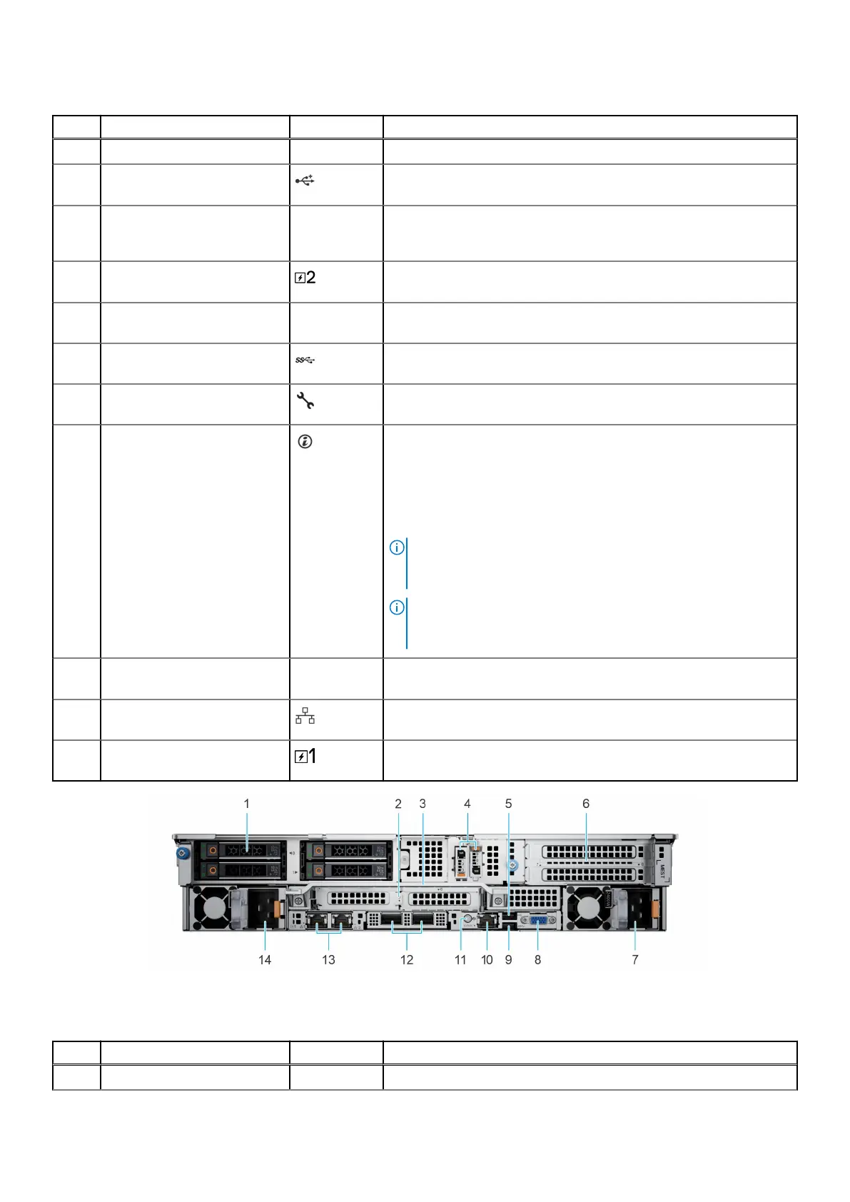
Table 10. Rear view of the system (continued)
Item Ports, panels, or slots Icon Description
5 Rear drive module N/A Enables you to install drives that are supported on your system.
6 USB 2.0 port (1) The USB port is 4-pin, 2.0-compliant. This port enables you to
connect USB devices to the system.
7 PCIe expansion card riser 4
(slot 7 and slot 8)
N/A The expansion card riser enables you to connect PCI Express
expansion cards. For more information on the expansion cards that
are supported on your system,
8 Power supply unit (PSU 2) For more information about the PSU configurations, see
www.dell.com/poweredgemanuals section.
9 VGA port N/A Enables you to connect a display device to the system. For more
information, see www.dell.com/poweredgemanuals section.
10 USB 3.0 port The USB port is 9-pin and 3.0-compliant. This port enables you to
connect USB devices to the system.
11 iDRAC9 ethernet port Enables you to remotely access iDRAC. For more information, see
www.dell.com/poweredgemanuals section.
12 System Identification (ID)
button
The System Identification (ID) button is available on the front and
back of the system. Press the button to identify a system in a rack
by turning on the system ID button. You can also use the system ID
button to reset iDRAC and to access BIOS using the step through
mode. When pressed, the system ID LED in the back panel blinks until
either the front or rear button is pressed again. Press the button to
toggle between on or off mode.
NOTE: If the server stops responding during POST, press and
hold the System ID button for more than five seconds to enter
the BIOS progress mode
NOTE: To reset the iDRAC (if not disabled on the iDRAC setup
page by pressing F2 during system boot), press and hold the
System ID button for more than 15 seconds.
13 OCP NIC card N/A The OCP NIC card supports OCP 3.0. The NIC ports are integrated
on the OCP card which is connected to the system board.
14 NIC ports The NIC ports are embedded on the LOM card that is connected to
the system board.
15 Power supply unit (PSU1) PSU1 is the primary PSU of the system. For more information, see
www.dell.com/poweredgemanuals section.
Figure 11. Rear view of the system with 4 x 2.5-inch rear drive module
Table 11. Rear view of the system
Item Ports, panels, or slots Icon Description
1 Drives N/A Enables you to install drives that are supported on your system.
16 System overview
 Loading...