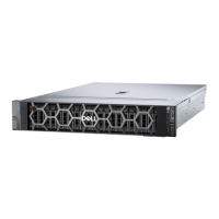
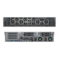
Figure 14. Inside the system with processor liquid cooling module
1.
Rear Handle 2. Riser 1 filler
3. BOSS N1 card slot 4. Power supply unit (PSU 1)
5. System board 6. Processor 1 Liquid Cooling modules
7. Memory DIMM socket for processor 1 8. Cooling fans
9. PERC Controller 10. Drive backplane cover
11. Service tag 12. Expander
13. Cooling fan cage assembly 14. Memory DIMM socket for processor 2
15. Processor 2 Liquid Cooling modules 16. Power supply unit (PSU 2)
17. Riser 3 filler 18. Intrusion switch module
19. Riser 4 filler
Locating the Express Service Code and Service Tag
The unique Express Service Code and Service Tag is used to identify the system. The information tag is located on the front of
the system that includes system information such as Service Tag, Express Service Code, Manufacture date, NIC, MAC address,
20
System overview
 Loading...
