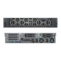
Figure 103. C7-10: 24 x 2.5-inch SAS4/SATA (w/ FPERC12) w/ 4 x 2.5-inch
NOTE:
Follow the sequential order as shown in the table to remove the cables, to install the cables follow the reverse
sequential order.
Table 101. 24 x 2.5-inch SAS4/SATA (w/ FPERC12) w/ 4 x 2.5-inch
Order From To
1 SIG_PWR_1 (system board power connector) BP_PWR_1 (backplane power connector)
2 SL3_CPU1_PA1 (signal connector on system
board)
CTRL_DST_PA1 (fPERC input connector)
3 SL4_CPU1_PB1 (signal connector on system
board)
CTRL_DST_PB1 (fPERC input connector)
4 CTRL_SRC_SB1 (fPERC controller connector) BP_DST_SB1 (backplane expander signal
connector)
5 CTRL_SRC_SA1 (fPERC controller connector) BP_DST_SA1 (backplane expander signal
connector)
6 SIG_PWR_2 (system board power connector) BP_PWR_2 (backplane power connector)
7 SIG_PWR_0 (system board power connector) BP_PWR_1 (rear backplane power connector)
8 BP_SRC_SA2 (backplane expander signal
connector)
BP_DST_SA1 (rear backplane signal connector)
and BP_DST_SB1 (rear backplane signal
connector)
PERC module
Removing the front mounting front PERC module
Prerequisites
1. Follow the safety guidelines listed in the Safety instructions.
2. Follow the procedure listed in the Before working inside your system.
136
Installing and removing system components
 Loading...
