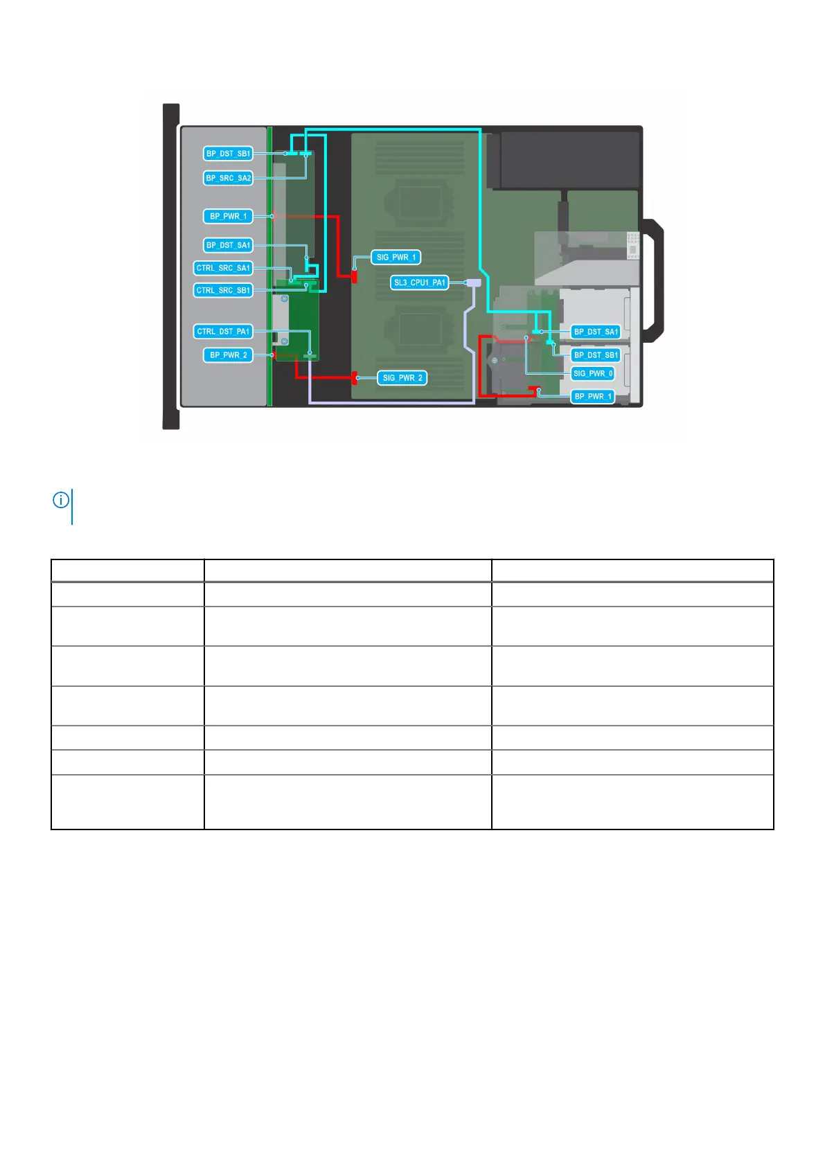
Figure 102. C7-9: 24 x 2.5-inch SAS4/SATA (w/ FPERC11) w/ 4 x 2.5-inch
NOTE:
Follow the sequential order as shown in the table to remove the cables, to install the cables follow the reverse
sequential order.
Table 100. 24 x 2.5-inch SAS4/SATA (w/ FPERC11) w/ 4 x 2.5-inch
Order From To
1 SIG_PWR_1 (system board power connector) BP_PWR_1 (backplane power connector)
2 SL3_CPU1_PA1 (signal connector on system
board)
CTRL_DST_PA1 (fPERC input connector)
3 CTRL_SRC_SB1 (fPERC controller connector) BP_DST_SB1 (backplane expander signal
connector)
4 CTRL_SRC_SA1 (fPERC controller connector) BP_DST_SA1 (backplane expander signal
connector)
5 SIG_PWR_2 (system board power connector) BP_PWR_2 (backplane power connector)
6 SIG_PWR_0 (system board power connector) BP_PWR_1 (rear backplane power connector)
7 BP_SRC_SA2 (backplane expander signal
connector)
BP_DST_SA1 (rear backplane signal connector)
and BP_DST_SB1 (rear backplane signal
connector)
Installing and removing system components 135
 Loading...