10
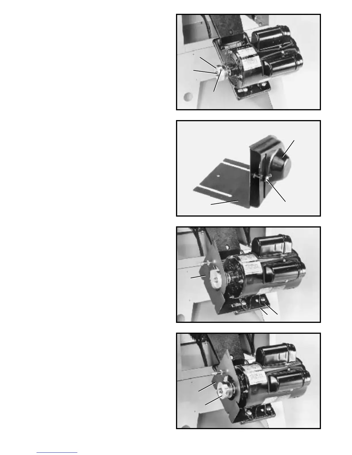
Fig. 16
Fig. 17
Fig. 18
Fig. 19
ASSEMBLING MOTO R
PULLEY, BELT AND
PULLEY GUARD, AND
DRIVE BELT
W ARNING: WHEN ASSEMBLING MO TO R PULLEY,
BELT A N D PULLEY GUARD, A N D DRIVE BELT, MAKE
CERTAIN THE MOTO R IS DISCONNECTED FROM
THEPOWERSOURCE.
1. Remove the motor shaft key that is t aped to the
motor.
2. Insert the key (A) Fig. 16, in the keyway on the motor
shaft. Assemble the motor pulley (B) on the motor shaft
as shown, with the hub of the pulley facing out. T ighten
set screw (C) against key (A) in motor shaft.
3. Remove wing nut and external tooth lockwasher (D)
Fig. 17, and outer cover (E) from belt and pulley guard (G).
4. Slide the belt and pulley guard bracket (G) Fig. 18,
between the motor plate (M) and motor mounting plate
(L), as shown.
5. Position belt and pulley guard bracket (G) Fig. 19, so
the motor pulley (B) is centered and through the hole in
the belt and pulley guard bracket, as shown. T ighten the
four hex nut s that fasten the motor to the motor mounting
plate.
6. Using a straight edge, align the motor pulley with the
arbor pulley. If necessary, adjust the motor pulley (B)
Fig. 19, in or out on the motor shaf t.
B
A
C
G
D
E
M
L
G
G
B
 Loading...