8
Fig. 9
Fig. 10
Fig. 11
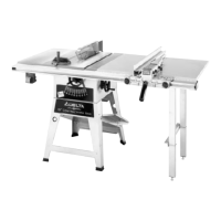
ASSEMBLING
SAW TO STAND
1. Fig. 8, illustrates the st and (B) completely assem-
bled.
2. Assemble rubber foot (A) Fig. 8, onto the end of
each stand leg (B). Insert grommet (C) into hole (D) in
st and leg.
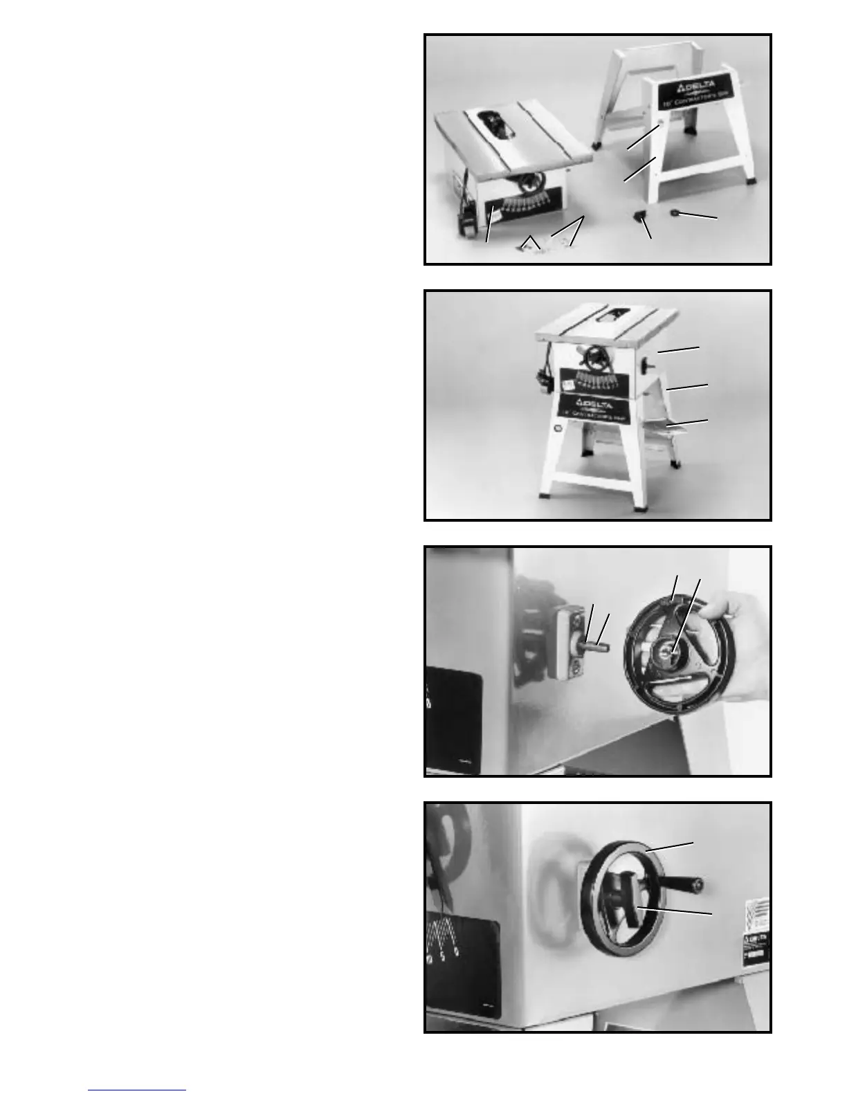
3. Carefully place saw (E) Fig. 9, onto saw st and (B).
Align eight holes in the top of st and (B) with mounting
holes in the bottom of saw (E) and fasten with eight screws ,
flat washers, lockwashers, and hex nuts (F) Fig. 8.
4. Fig. 9, illustrates the saw (E) assembled to the saw
st and (B). Carefully push down on the top of the saw until
the st and legs are positioned firmly on the floor surface
and securely tighten all saw and stand mounting hard-
ware. Notice that panel (G) is not only a support for a
st and, but also serves as a dust chute.
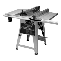
ASSEMBLING BLADE
TILTING HANDWHEEL
1. Assemble blade tilting handwheel (A) Fig. 10, to
shaft (B). Make cert ain slot (C) in handwheel is engaged
with roll pin (D) on the shaf t.
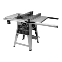
2. Thread locking lever (E) Fig. 11, onto shaf t.
3. Fig. 11, illustrates the blade tilting handwheel (A) and
locking lever (E) assembled to the saw.
E
B
G
D
B
A
C
A
E
Fig. 8
D
B
C
A
E
F
F