27
BACKLASH ADJUSTMENTS
FOR BLADE RAISING A N D
BLADETILTING MECHANISMS
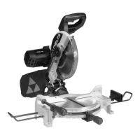
Af ter a period of extended use, if any play is detected in
the blade raising or blade tilting mechanisms, the follow -
ing adjustments should be made.
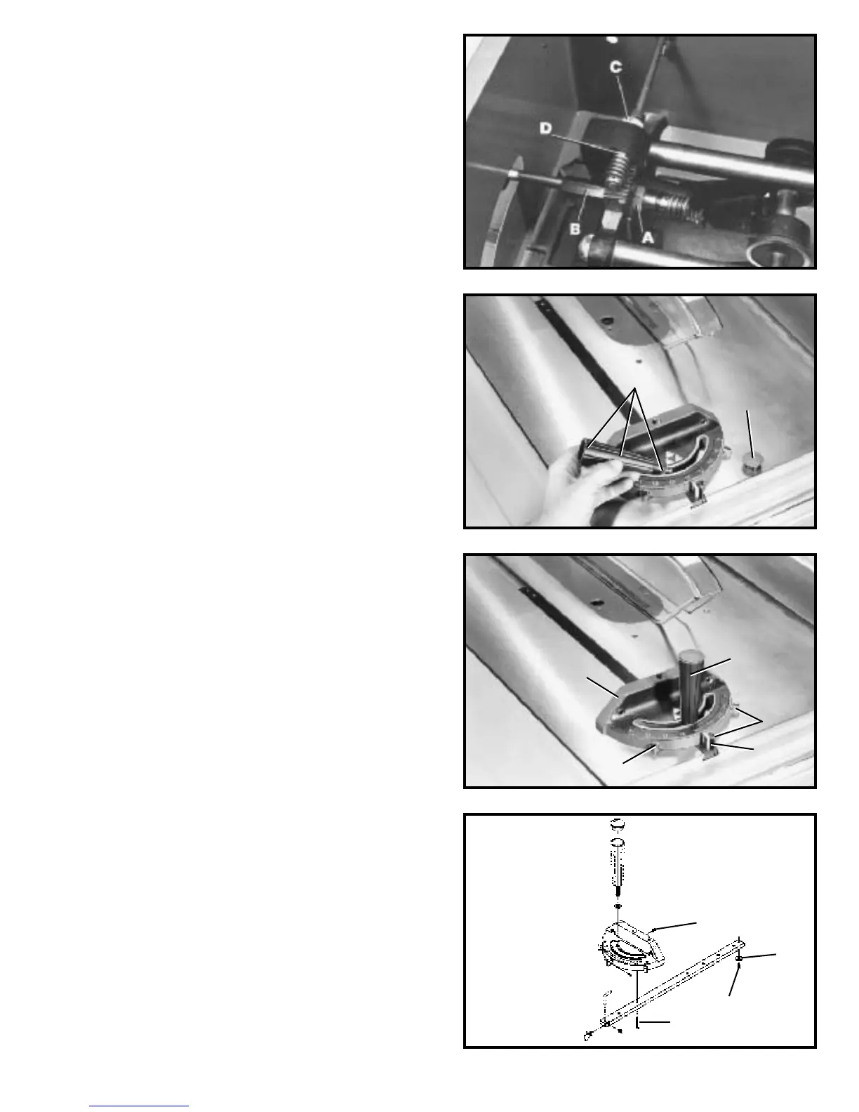
1. Make certain the machine is disconnected from
the power source.
2. NOTE: The machine has been turned upside down
and the blade removed for clarity and safety.
3. Adjusting blade raising mechanism - Loosen lock -
nut (A) Fig. 83, and turn eccentric sleeve (B) until all play
is removed in mechanism and tighten locknut (A).
4. Adjusting blade tilting mechanism - Loosen lock-
nut (C) Fig. 83, and turn eccentric (D) until all play is
removed in mechanism and tighten locknut (C).
Fig. 83
Fig. 84
Fig. 85
Fig. 86
K
A
A
B
D
B
C
H
E
F
G
MITER GAGEOPERATION
AND ADJUSTMENT
1. Insert the miter gage bar into the miter gage slot and
assemble the washer and lock handle (A) Fig. 84, to
the miter gage bar as shown. Insert cap (K) into top of
handle (A).
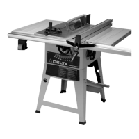
2. The miter gage is equipped with adjust able index
stops at 90 degrees and 45 degrees right and lef t.
Adjustment to the index stops can be made by tightening
or loosening the three adjusting screws (B) Fig. 85.
3.To rotate the miter gage, loosen lock knob (A) Fig. 85 ,
and move the body of the miter gage (C) to the desired
angle.
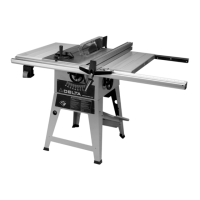
4. The miter gage body will stop at 90 degrees and 45
degrees both right and left. To rotate the miter gage body
past these point s, the stop link (D) Fig. 85, must be
moved up and out of the way.
5. The miter gage is equipped with a special washer (E)
Fig. 86, and flat head screw (F), which are to be assem -
bled to the end of the miter gage bar.
6. The head of the miter gage pivot s on a special
tapered screw (G) that fastens the head to the miter gage
bar. If the miter gage head does not pivot freely, or pivot s
too freely, it can be adjusted by loosening set screw (H)
Fig. 86, and turning the screw (G), in or out. Be cert ain to
tighten screw (H) af ter adjustment is made.