7
ASSEMBLY INSTRUCTIONS
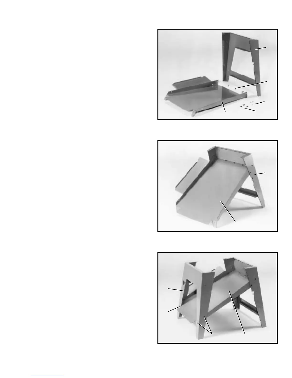
Fig. 5
Fig. 6
Fig. 7
ASSEMBLING SAW STAND
1. Assemble the dust chute and support panel (A)
Fig. 5, to the inside of the front st and panel (B) with three
#10 x 1/2 † sheet metal screws (C), four #10-32 x 1/2 †
screws (D), and four hex nuts (E). Fig. 6, illustrates the
dust chute and support panel (A) assembled to the front
of st and (B). NOTE: The front st and panel will have the
saw identity labels facing you. Do not completely tighten
the st and hardware at this time. Also, make certain the
dust chute/support panel (A) Fig. 6, is located under the
lip of front stand panel (B).
2. Assemble the other end of dust chute and support
panel (A) Fig. 7, to rear st and panel (F) as shown with
four #10-32 x 1/2 † screws and hex nuts, three of which
are shown at (D). NOTE: Do not completely tighten st and
hardware at this time.
B
C
E
D
A
A
B
A
D
D
F