25
Fig. 75
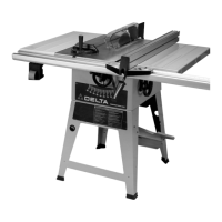
CURRENT-CARRYING PRONGS
GROUNDPRONG
240 VOLT
240 VOLT,
SINGLE PHASE OPERATION
The motor supplied with your saw is a dual voltage,
120/240 volt motor. If it is desired to operate your saw at
240 volt s, single phase, it is necessary to reconnect the
motor leads in the motor junction box by following the in-
structions given on the motor nameplate. W ARNING: MAKE
SURE MOTO R IS DISCONNECTED FROMPOWER
SOURCEBEFORERECONNECTING MOTO R LEADS.It
is also necessary to replace the 120 volt plug, supplied
with the motor, with a UL/CSA Listed plug suit able for
240 volt s and the rated current of the saw as illustrated
in Fig. 75. Cont act your local Authorized Delt a Service
Center or qualified electrician for proper procedures to
inst all the plug. The saw must comply with all local and
national electrical codes af ter the 240 volt plug is
inst alled.
The saw with a 240 volt plug should only be connected
to an outlet having the same configuration as the plug
illustrated in Fig. 75. No adapter is available or should be
used with the 240 Volt plug.
CAUTION: IN ALL CASES MAKECERTAIN THE RE-
CEPTACLE IN QUESTION IS PROPERLY GROUNDED.
IF Y O U AR E NOT SURE, H AVE A CERTIFIED ELEC-
TRICIAN CHECK THERECEPTACLE.
FASTENING STAND TO SUPPORTING SURFACE
IF DURING OPERATION THERE ISANY TENDENCY FOR THE SAW TO TIP OVER, SLIDE O R W A LK ON THE
SUPPORTING SURFACE, THE S AW STA N D C A N B E SECUREDTO THE FLOOR SURFACE. THE RUBBER
FEET OF THE STAND FEATURE HOLES WHICH ALLOWEASY MOUNTING WITHOUT REMOVING THE SAW
FROMTHESTAND.
OPERATING CONTROLS AND ADJUSTMENTS
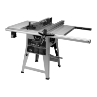
Fig. 76
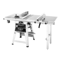
Fig. 77
A
B
A
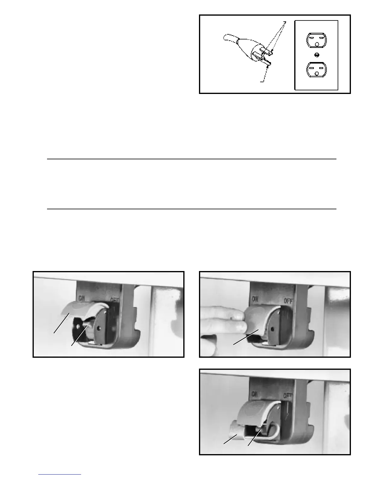
Fig. 78
LOCKING SWITCH IN
THE OFF POSITION
W e suggest that when the saw is not in use, the on/off
switch trigger (B) Fig. 78, be locked in the OFF position
using a padlock (C) through the two holes in the switch
plate, as shown.
C
B
STARTING AND STOPPING SAW
1. The on/off switch is located underneath the switch shield (A) Fig. 76. To turn the saw ON, move
switch trigger (B) to the up position.
2. To turn the saw OFF, simply push down on switch shield (A) Fig. 77.
 Loading...