12
Fig. 24
Fig. 25
Fig. 26
Fig. 27
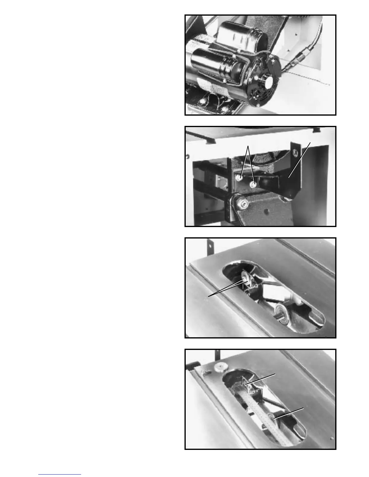
2. Fig. 24, illustrates the motor cord connected to the
switch assembly.
ASSEMBLING
BLADE GUARD AND
SPLITTER ASSEMBLY
W ARNING: M A K E CERTAIN THE SAW IS DISCON-
NECTED FROMTHEPOWERSOURCE.
1. Fasten the rear splitter mounting bracket (A) Fig. 25,
to the rear trunnion using the two 3/4 † hex head screws
(B) and flat washers. Do not completely tighten the two
screws (B) at this time.
2. W ith wrenches supplied, remove the saw blade from
the saw. Refer to section CHANGING THE SAW BLADE
on p age 28, of this manual. Raise saw arbor to it s high -
est position.
3. Remove screw and large washer (C) Fig. 26, from
the inside splitter mounting bracket.
4. Using a straight edge, check to see if the top and
bottom of the inside splitter bracket (D) Fig. 27, is aligned
with the inner arbor flange (E), as shown.
B
A
C
D
E
 Loading...