9
MOTOR
The motor shipped with your saw is a 1-1/2 H.P., Ball Bearing, Cap acitor S tart/Capacitor Run, 115/230
V olt motor.
This motor has been specially selected to best supply power to your machine and the relative safety of
the machine is enhanced by its use. We, therefore, strongly suggest that only this motor be used, as
the use of other motors may be detrimental to the performance and safety of the saw.
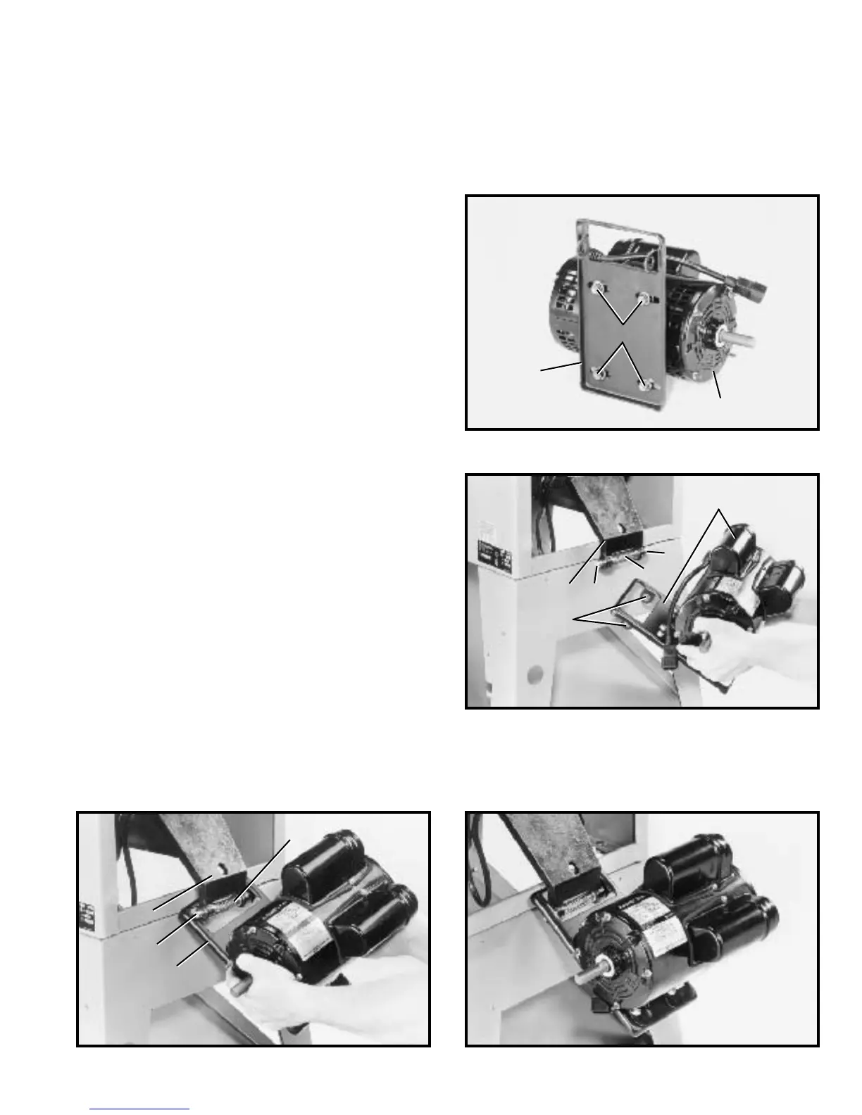
Fig. 12
Fig. 15Fig. 14
ASSEMBLING MOTO R TO
MOTO R MOUNTING PLATE
W ARNING: WHENASSEMBLING THE MO TO R TO THE
MOTO RMOUNTING PLATE, MAKE CERTAIN THESAW
IS DISCONNECTED FROMTHEPOWERSOURCE.
1. Assemble the motor (A) to the motor mounting plate
(B) as shown in Fig. 12, using four carriage bolt s, flat
washers, star washers, and hex nuts (C).
NOTE: Do not completely tighten the hex nut s at this
time.
ASSEMBLING MOTO R
AND MOTO R MOUNTING
PLATE TO SAW
W ARNING: WHENASSEMBLING THE MOTO R AND
MOTO R MOUNTING PLATE TO THE SAW , MAKE CER-
TAIN THE S AW IS DISCONNECTED FROMTHEPOWER
SOURCE.
1. Insert two pins (X) Fig. 13, into holes (D) in each side
of bracket (B). Assemble spring (Y) onto ends of pins (B)
as shown.
2. Position motor and motor mounting plate (A) Fig. 13,
below bracket (B) to allow bracket arm to slide through
large opening in motor mounting plate (A).
3. Depress plungers (X) Fig. 14, on both sides of brack-
et (B) and rot ate motor mounting plate (A) until plungers
(X) are engaged in holes (D) Fig. 13, of motor mounting
plate (A).
A
C
B
B
D
A
C
B
C
A
Fig. 13
4. Fig. 15, illustrates the motor and motor mounting
plate assembled to the rear of the saw.
X
Y
X