23
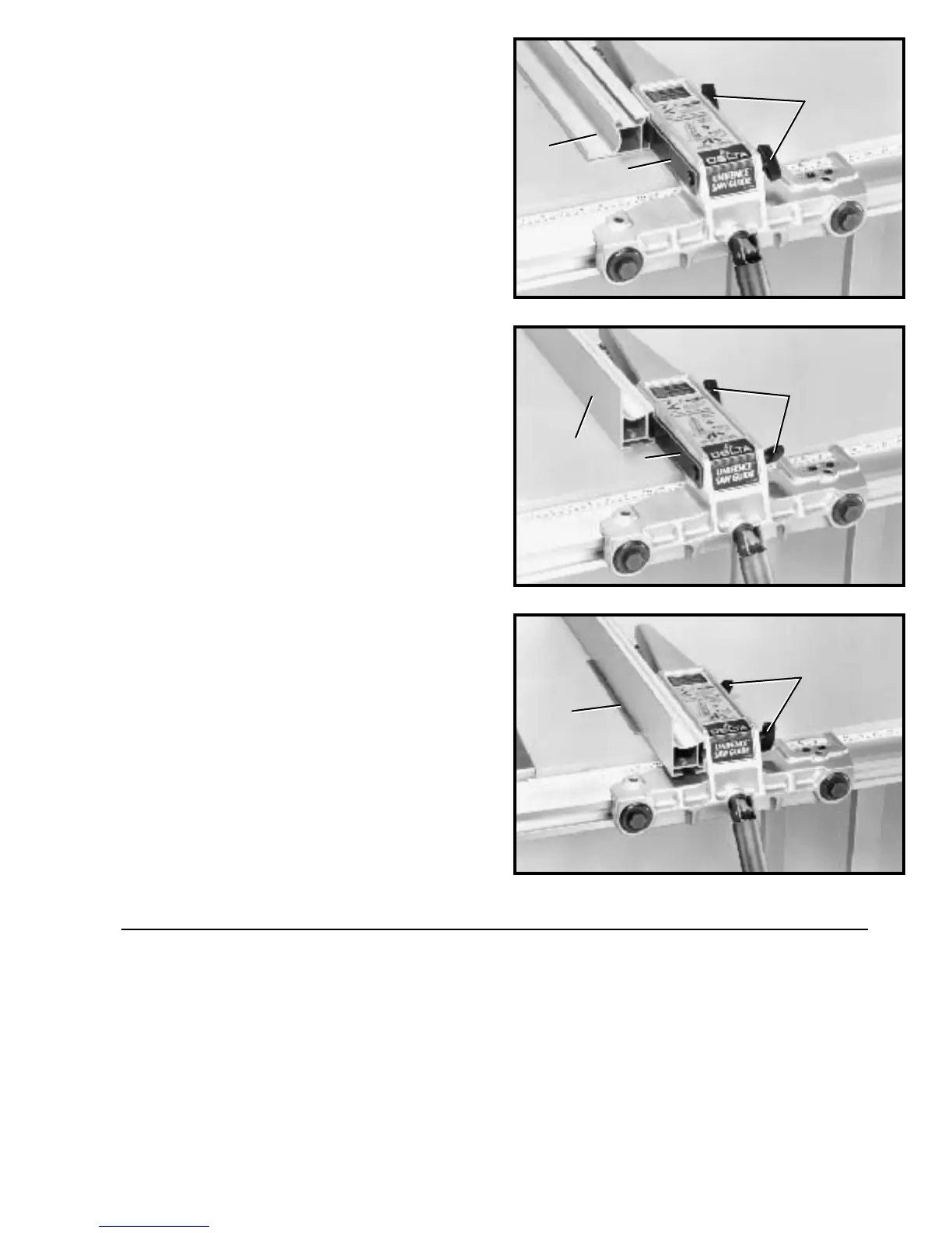
Fig. 70
Fig. 71
Fig. 69
ASSEMBLING UNIFENCE
TO UNIFENCE BODY
1. The fence (A) can be assembled to clamp plate (B)
in either the horizont al position as shown in Fig. 69, or
the vertical position as shown in Fig. 70. Make cert ain the
two lock knobs (C), are loose and slide fence (A) onto
clamp plate (B) as shown. Then tighten the two lock
knobs (C).
2. For most normal ripping operations, the bottom of
the fence should be positioned slightly above the table
surface. Loosen two lock knobs (C) Fig. 71, and place a
thin object such as a ruler (D) between the t able and
fence, as shown. Then tighten two lock knobs (C).
CONNECTING SAW TO POWERSOURCE
POWERCONNECTIONS
A sep arate electrical circuit should be used for your tools. This circuit should not be less than #12
wire and should be protected with a 20 Amp fuse. Have a certified electrician replace or rep air a
worn cord immediately.Before connecting the motor to a power line, make sure the switch is in
the OFF position and be sure that the electric current is of the same characteristics as st amped
on the motor nameplate. Running on low voltage will damage the motor.
C
B
A
C
A
B
C
D