26
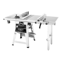
Fig. 79
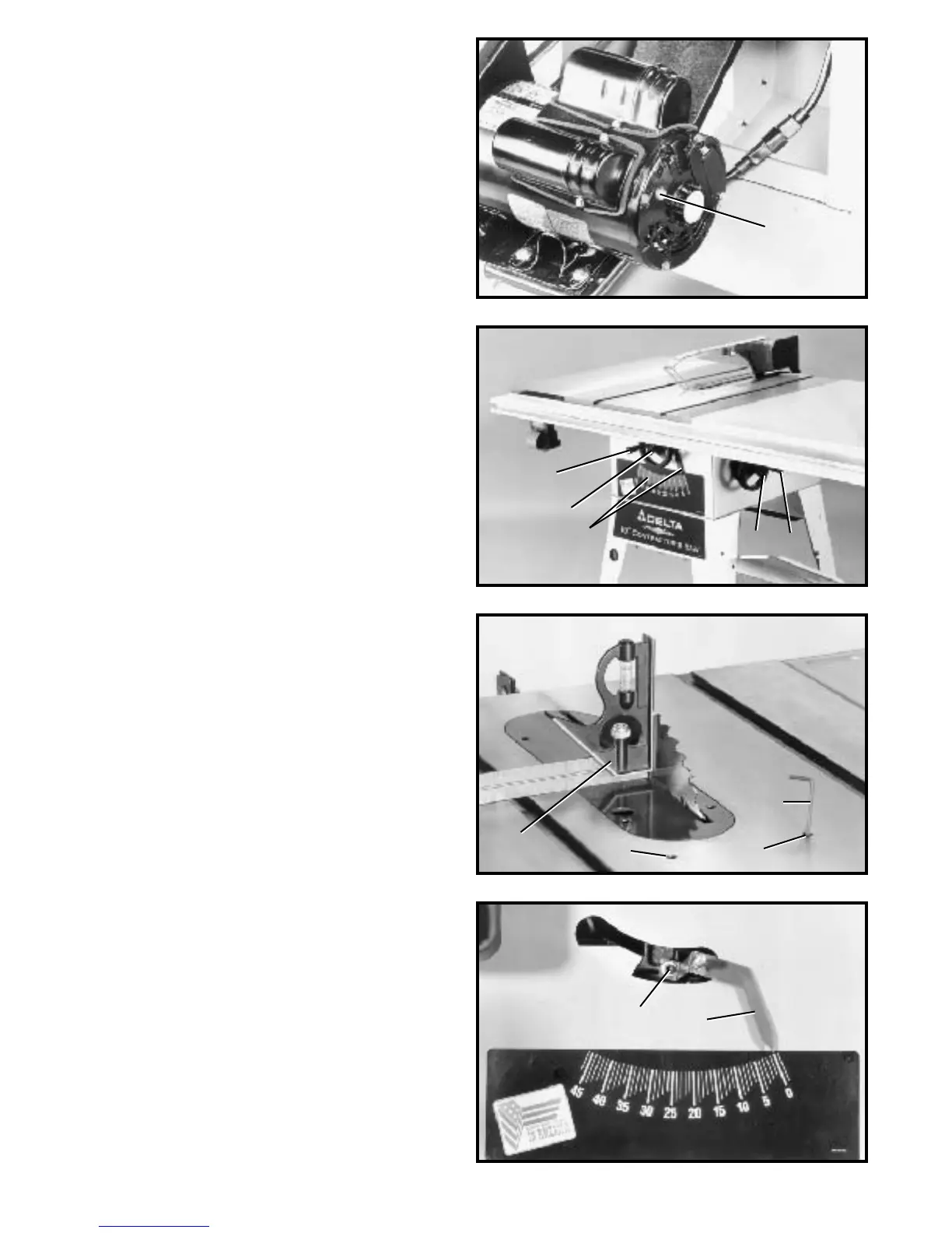
Fig. 80
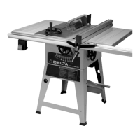
Fig. 81
OVERLOAD PROTECTION
The motor recommended for use with your saw is
equipped with a reset overload relay button (A) Fig. 79. If
the motor shuts off or fails to st art due to overloading
(cutting stock too fast, using a dull blade, using the saw
beyond its cap acity , etc.), or low volt age, turn the switch
to the OFF position, let the motor cool three to five
minutes and push the reset button (A), which will reset
the overload device.The motor can then be turned on
again in the usual manner.
RAISING AND LOWERING
THE BLADE
To raise the saw blade, loosen lock knob (A) Fig. 80, and
turn the blade raising handwheel (B) clockwise. When
the blade is at the desired height, tighten lock knob (A).
To lower the blade, loosen lock knob (A) Fig. 80, and turn
the handwheel (B) counterclockwise. NOTE: One full turn
of the handwheel will change blade height approxi-
mately 1/4†.
TILTING THE BLADE
To tilt the saw blade for bevel cutting, loosen lock knob
(C) Fig. 80, and turn the tilting handwheel (D). When the
desired blade angle shown on scale and pointer (E) is
obtained, tighten lock knob (C).
ADJUSTING 90 DEGREE A N D
45 DEGREE POSITIVE STO P S
Your saw is equipped with positive stop s that will quickly
and accurately position the saw blade at 90 degrees and
45 degrees to the table. To check and adjust the positive
stop s, proceed as follows:
1. W ARNING: When adjusting the positive stops,
make certain the machine is disconnected from the
power source.
2. Raise the saw blade to it s highest position.
3. Set the blade at 90 degrees to the t able by turning
the blade tilting handwheel counterclockwise as far as it
will go.
4. Using a combination square (A) Fig. 81, check to see
if the blade is at 90 degrees to the t able surface as
shown.
5. If the blade is not at 90 degrees to the t able, loosen
set screw (B) Fig. 81 with supplied wrench (C), and turn
the blade tilting handwheel until you are certain the blade
is at 90 degrees to the t able. T urn set screw (B) clock -
wise until it bottoms.
A
C
BF
A
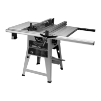
Fig. 82
E
D
6. Adjust the pointer (D) Fig. 82, to point to the zero
degree mark on the scale by loosening screw (E), adjust-
ing pointer (D), and tightening screw (E).
7. Turn the blade tilting handwheel clockwise as far as
it will go and using a combination square, check to see if
the blade is at 45 degrees to the t able.
8. If the blade is not at 45 degrees to the t able, loosen
set screw (F) Fig. 82, and turn blade tilting handwheel
until you are cert ain the blade is 45 degrees to the t able.
Turn set screw (F) clockwise until it bottoms.
A
B
C
D
E