16
Fig. 40
Fig. 41
Fig. 42
Fig. 44Fig. 43
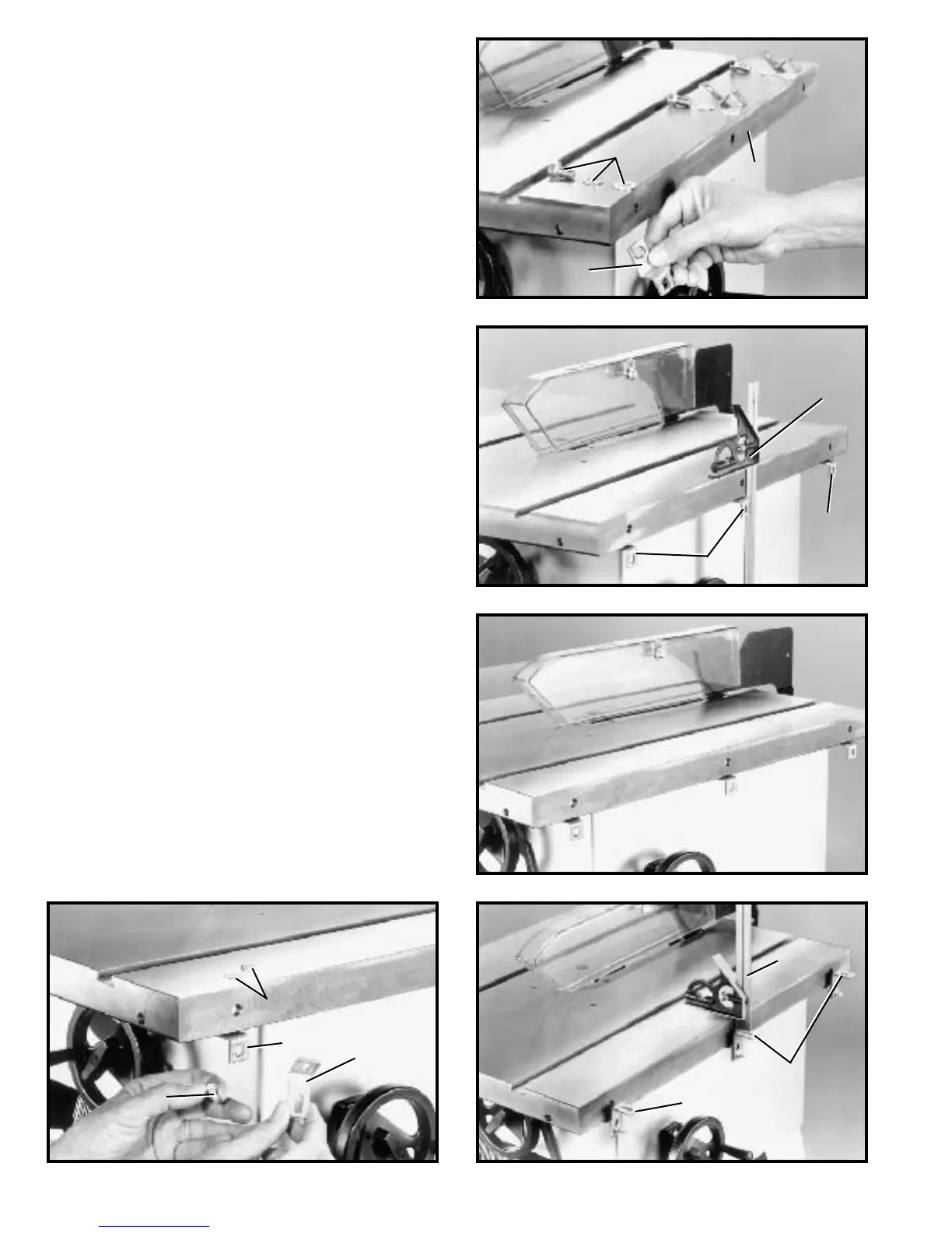
ASSEMBLING TABLE
MOUNTING BRACKETS
TO SAW TABLE
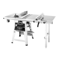
1. Assemble Z-brackets (A) Fig. 40, to the three t apped
holes at the inside edge on the right side of saw t able (B),
using three 7/16-20 x 3/4 † hex head screws (C) with flat
washers and lockwashers.
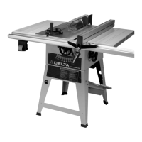
2. Using a square (D) Fig. 41, make cert ain the
Z-brackets (A) are perpendicular to the saw t able as
shown. Also, lift upward on Z-brackets (A) while tighten -
ing screws (C) to eliminate any play.
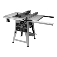
3. Fig. 42, illustrates the Z-brackets assembled to the
saw blade.
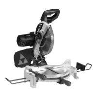
4. Assemble angle bracket (E) Fig. 43, onto Z-bracket
(A) using 1/4-20 x 3/4 † carriage bolt (F) with flat washer
and hex nut. IMPORTANT:The longer leg of angle
bracket (E) must be secured to Z-bracket (A). Assemble
the remaining two angle brackets to the edge of the t able
in the same manner.
5. Using a square (G) Fig. 44, set the angle brackets so
they are approximately 3/4†from the top of the saw t able.
Final adjustments to angle bracket s will be made later.
B
C
A
D
A
A
F
A
E
F
E
E
G
 Loading...