11
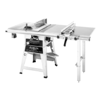
Fig. 20
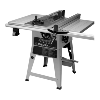
Fig. 21
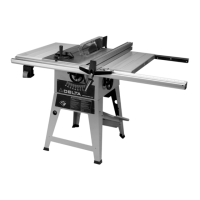
Fig. 22
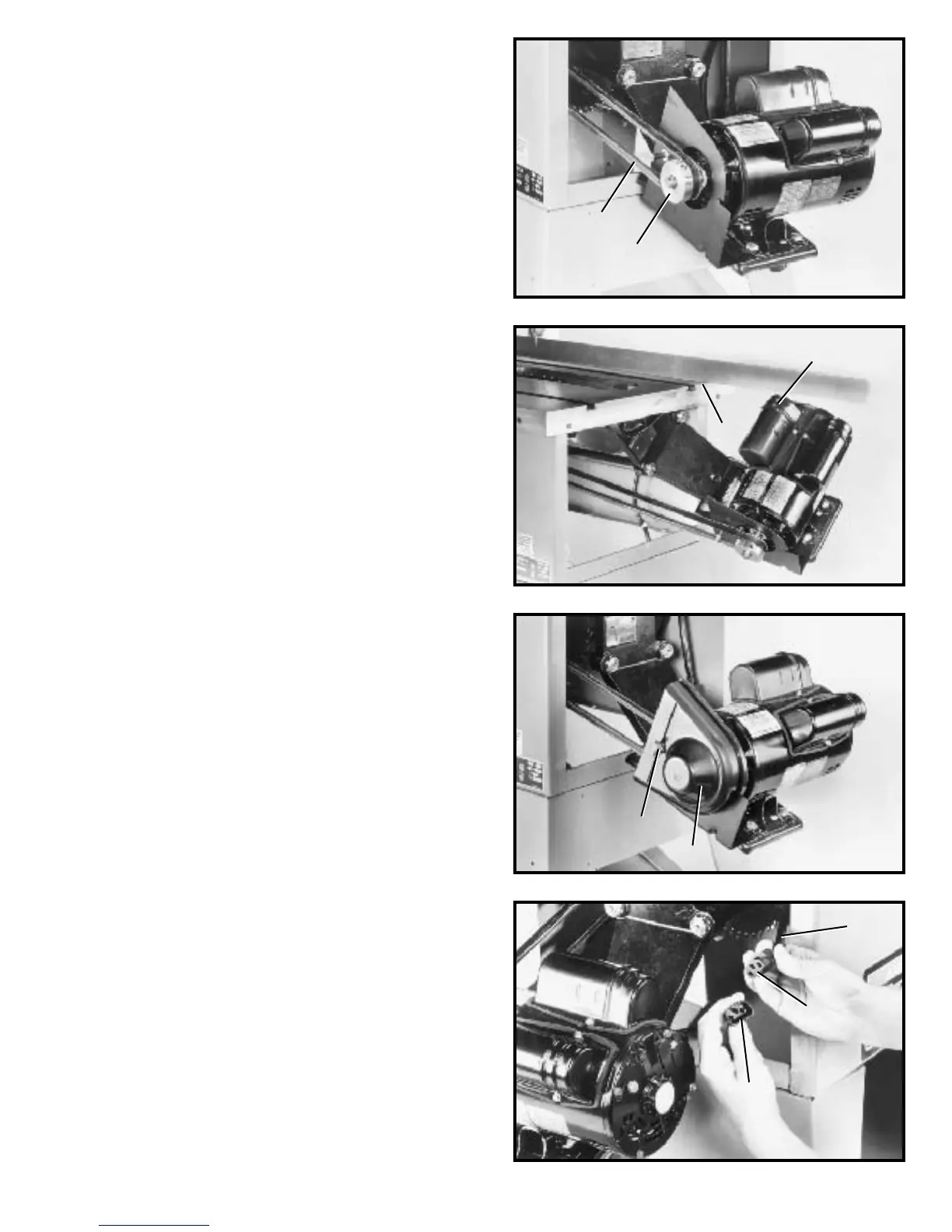
Fig. 23
7.Lif t the motor and assemble the drive belt (H) Fig. 20,
to the arbor pulley and motor pulley (B). The weight of
the motor will provide the correct belt tension.
8. W ARNING: IMMEDIATELY AFTER ASSEMBLING
T H E B E LT, RAISE T H E S AW BLADE TO ITS MAXIMUM
HEIGHT AN D TILT THE S AW BLADE TO 45 DEGREES.
CHECKTO SEEIF THE MOTO R END BELL (J) FIG. 21,
ISBELOWTHETOPOFTHETABLE SURFACE (K). IF
THE MOTO R END BELL (J) IS ABOVE THETOPOF
THETABLESURFACE, THE M O TOR MUST BE MOVED
TO THE LEFT UNTIL Y O U A R E CERTAIN THE END
BELL (J)OFTHEMOTORISBELOWTHETOP OF
THETABLE SURFACE. THEN RE-ALIGN THE M O TO R
PULLEY TO THE ARBORPULLEY.
9. Assemble the outer cover (E) Fig. 22, of the belt and
pulley guard assembly, which was removed in STEP 3,
and fasten with external tooth lockwasher and wing nut
(D). IMPORTANT:Make certain the outer cover does not
interfere with the drive belt and the motor pulley.
CONNECTING MOTO R CORD
TO SWITCH ASSEMBLY
W ARNING: BEFORE CONNECTING MOTO R CORDTO
THE SWITCH ASSEMBLY, MAKE CERTAIN THE SAW
IS DISCONNECTED FROMTHEPOWERSOURCE.
1. Insert the pronged motor plug (A) Fig. 23, into the
female receptacle (B) of switch-to-motor cord (C).
H
B
K
J
D
E
C
B
A
 Loading...